In the planning of PCB circuit board drawings, you will often see people asking questions about the serpentine line. Usually, the places where we can see the serpentine lines are mostly high-speed high-density boards, like the boards with serpentine lines are more high-end, and it is a master who knows how to draw serpentine lines. There are also many articles about snake-shaped lines on the Internet, and I always feel that the content of some posts will mislead novices, cause confusion to people, and create some artificial obstacles. So let's take a look at the practical application of the side serpentine line.
Analyze what are the applications of serpentine lines in PCB circuit board design
To understand the serpentine line, let's talk about PCB routing first. This concept does not seem to need to be introduced. The inconvenience that hardware engineers do every day is wiring work. Every trace on the PCB is drawn one by one by the hardware engineer. What can we say? In fact, this simple trace also contains many knowledge points that we usually overlook. For example, the concept of microstrip line and stripline. In short, the microstrip line is the trace that runs on the surface of the PCB board, and the stripline is the trace that runs on the inner layer of the PCB. What is the difference between these two lines? The reference plane of the microstrip line is the ground plane of the inner layer of the PCB, and the other side of the trace is exposed to the air, so that the dielectric constant around the trace is not the same. For example, the dielectric constant of our commonly used FR4 substrate is about 4.2, and the dielectric constant of air is 1. There are reference planes on both the upper and lower sides of the strip line. The entire trace is embedded near the PCB substrate, and the dielectric constant around the trace is the same. This also constitutes the transmission of TEM waves on the strip line, and the transmission of quasi-TEM waves on the microstrip line. Why is it a quasi-TEM wave? It is caused by the phase mismatch at the interface between the air and the PCB substrate. What is TEM wave? ... If we dig deeper on this issue, we will not be able to finish it in ten and a half months. To make a long story short, whether it is a microstrip line or a stripline, their effect is nothing more than carrying signals, whether digital signals or analog signals. These signals are transmitted in the form of electromagnetic waves from one end to the other in the trace. Since it is a wave, there must be speed. What is the speed of the signal on the PCB trace? Depending on the difference in dielectric constant, the speed is also different. The propagation speed of electromagnetic waves in the air is the well-known speed of light. The propagation velocity in other media must be calculated by the following formula:

V=C/Er0.5
In the meantime, V is the propagation speed in the medium, C is the speed of light, and Er is the dielectric constant of the medium. Through this formula, we can easily calculate the transmission speed of the signal on the PCB trace. For example, we simply take the dielectric constant of the FR4 substrate into the formula calculation, which means that the transmission speed of the signal in the FR4 substrate is half the speed of light. However, for the microstrip line on the surface layer, because half is in the air and half is in the substrate, the dielectric constant will be slightly reduced, so the transmission speed will be slightly faster than the strip line. The commonly used empirical data is that the trace delay of the microstrip line is about 140ps/inch, and the trace delay of the stripline is about 166ps/inch.
As mentioned above, there is only one purpose, that is, the transmission of the signal on the PCB is delayed! In other words, the signal is not transmitted from one pin to another pin through the trace in an instant. . Although the signal transmission speed is very fast, as long as the trace length is long enough, it will still affect the signal transmission. For example, for a 1GHz signal, the period is 1ns, and the time of the rising or falling edge is about one-tenth of the period, then it is 100ps. If the length of our trace exceeds 1 inch (approximately 2.54 cm), then the delay of transmission will be more than a rising edge. If the trace exceeds 8 inches (approximately 20 cm), then the delay can be a full cycle! It turns out that PCB has such a big influence, it is very common for our boards to have more than 1inch traces. So will the delay affect the normal work of the board? Looking at the practice system, if there is only one signal, and other signals do not want to be closed, then the delay does not seem to have any effect. However, in the high-speed system, this delay will have a real effect.
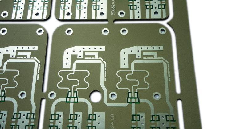
For example, our common memory particles are connected in the form of a bus, with data lines, address lines, clocks, and control lines. Let's look at our video interface again. No matter how many channels are HDMI or DVI, they will include data channels and clock channels. Perhaps it is some bus protocol, all of which are synchronous transmission of data and clock. Then, in the practical high-speed system, these clock signals and data signals are synchronously sent from the main chip. If our PCB layout is poor, the length of the clock signal and the data signal is very different. It is easy to constitute wrong sampling of data, and then the whole system will not work properly. What should we do to solve this problem? Naturally we would think of lengthening the short-length traces so that the length of the traces in the same group is similar, then the delay will be the same? Then how to lengthen the traces? !Bingo! Finally, it's not easy to return to the topic. This is the primary effect of the serpentine line in the high-speed system. Winding, equal length. It is so simple. The serpentine line is used to wind the equal length. After drawing the serpentine line, we can achieve the same length of the same group of signals, so that after the signal is received by the chip, there will be no different delays due to the PCB circuit board traces. The composition data is wrongly collected. The serpentine line is the same as the traces on other PCB boards. They are used to connect signals. They only go longer and don't have it. So the serpentine line is not deep and not too complicated.
Since it is the same as other traces, some commonly used wiring rules are also applicable to serpentine lines. At the same time, because of the special structure of serpentine lines, you should pay attention to it when wiring. For example, try to keep the serpentine lines parallel to each other farther. Shorter, it is the old saying goes around a big bend, don't go too dense and too small in a small area. This all helps to reduce signal interference. The serpentine line must have a bad influence on the signal due to the artificial increase of the line length, so as long as it can meet the timing requirements in the system, do not use it if it is not needed. Some engineers use DDR or high-speed signals to make the entire group equal length, and the snake-shaped lines fly all over the board. It seems that this is a better wiring. In practice, this is a manifestation of taking idle time and irresponsible. Many places that do not need to be wound are wound, not only wasting the area of the board, but also reducing the signal quality. We should calculate the delayed redundancy based on the actual signal speed requirements, and then determine the board wiring rules.
In addition to the effect of equal length, I have seen several other effects of the serpentine line that are often mentioned in articles on the Internet. Here is also a brief introduction.
1. A commonly seen argument is the effect of impedance matching. This argument is very strange. The impedance of PCB traces is related to the line width, the dielectric constant, and the distance of the reference plane. When is it related to the serpentine line? ?When does the shape of the trace affect the impedance? I don't know where the source of this statement comes from.
2. There is also a filtering effect. This effect cannot be said to be absent, but there should be no filtering effect in digital circuits. Perhaps we don’t need to use this function in digital circuits. In the radio frequency circuit, the serpentine trace can form an LC circuit. If it has a filtering effect on the signal of a certain frequency, it is still the past.
3. Inductance, this can be. All traces on the original PCB have parasitic inductance. It is possible to do some PCB inductors.
4. Accept the antenna, this can be. We can see this effect on some mobile phones or radios. Some antennas are made with PCB traces.
5. Fuse, this effect makes me puzzled. How does the short and narrow serpentine wire have the effect of a fuse? If the current is large, it will blow? The board is not useless. The price of this fuse is too great. I really don’t understand what kind of application it will be used in. .
After the above introduction, we can clearly understand that the serpentine line has some special effects near the analog or RF circuit board, which is determined by the characteristics of the microstrip line. In the digital circuit planning, the serpentine line is used to complete the timing matching effect of equal length. In addition, the serpentine line will have an impact on the signal quality, so the system requirements should be clear in the system, the system redundancy should be calculated according to practical requirements, and the serpentine line should be used cautiously.