One of the functions of integrated circuit packaging is to protect the environment of the chip and avoid contact between the chip and the outside air. Therefore, it is necessary to adopt different processing methods and select different packaging materials according to the specific requirements and use places of different types of integrated circuits to ensure that the airtightness of the packaging structure meets the specified requirements. The early packaging materials for integrated circuits are made of a mixture of organic resin and wax, and the packaging is realized by filling or infusion. Obviously, the reliability is very poor. Rubber was also used for sealing, but it was eliminated due to its unsatisfactory heat, oil and electrical properties. Currently, the most widely used and most reliable airtight sealing materials are glass-metal sealing, ceramic-metal sealing and low-melting glass-ceramic sealing. In the need of mass production and cost reduction, a large number of plastic model packaging has emerged. It is completed by heating and pressing thermosetting resin through a mold. Its reliability depends on the characteristics and molding conditions of the organic resin and additives, but due to its resistance It has poor thermal properties and hygroscopicity, and cannot be compared with other sealing materials. It is still a semi-airtight or non-airtight sealing material. With the maturity of chip technology and the rapid improvement of chip yield, the cost of rear sealing accounts for an increasing proportion of the cost of the entire integrated circuit. The changes and development of packaging technology are changing with each passing day and it is dizzying.
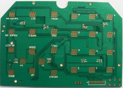
Each chip has a datasheet, and there will be application descriptions, structural packaging, material numbers and other descriptions on the datashe tool. When making Decal in Power PCB, you need to refer to the structure package description in the datasheet, which contains the size, shape, order, etc. of each pad.
List of chip packaging methods:
1. BGA (ball grid array)
A display of spherical contacts, one of the surface mount packages. On the back of the printed circuit board, spherical bumps are produced in the display mode to replace the pins, and the LSI chip is assembled on the front side of the printed circuit board, and then sealed by molding resin or potting. Also known as bump display carrier (PAC). Pins can exceed 200, which is a package for multi-pin LSI. The package body can also be made smaller than QFP (Quad Flat Package). For example, a 360-pin BGA with a pin center distance of 1.5mm is only 31mm square; while a 304-pin QFP with a pin center distance of 0.5mm is 40mm square. And BGA does not have to worry about pin deformation like QFP. This package was developed by Motorola Corporation of the United States. It was first adopted in portable phones and other devices, and may be popularized in personal computers in the United States in the future. Initially, the BGA pin (bump) center distance was 1.5mm, and the number of pins was 225. There are also some LSI manufacturers that are developing 500-pin BGAs. The problem with BGA is the visual inspection after reflow soldering. It is not yet clear whether an effective visual inspection method is available. Some believe that due to the large center distance of welding, the connection can be regarded as stable and can only be processed through functional inspection. The American Motorola company calls the package sealed with molded resin OMPAC, and the package sealed by the potting method is called GPAC (see OMPAC and GPAC).
2. BQFP (quad flat package with bumper)
Four-side pin flat package with cushion. One of the QFP packages, the four corners of the package body are provided with protrusions (buffer pads) to prevent bending and deformation of the pins during transportation. American semiconductor manufacturers mainly use this package in circuits such as microprocessors and ASICs. The pin center distance is 0.635mm, and the pin number is about 84 to 196 (see QFP).
3. Butt welding PGA (butt joint pin grid array)
Another name for surface mount PGA (see surface mount PGA).
4. C-(ceramic)
Indicates the mark of the ceramic package. For example, CDIP stands for ceramic DIP. It is a mark that is often used in practice.
5. Cerdip
Ceramic dual in-line package sealed with glass, used for ECL RAM, DSP (digital signal processor) and other circuits. Cerdip with glass window is used for ultraviolet erasable EPROM and microcomputer circuit with EPROM inside. The pin center distance is 2.54mm, and the number of pins is from 8 to 42. In Japan, this package is expressed as DIP-G (G means glass seal).
6. Cerquad
One of the surface mount packages, the ceramic QFP under hermetic sealing, is used to package logic LSI circuits such as DSP. Cerquad with windows is used to encapsulate EPROM circuits. The heat dissipation is better than that of plastic QFP, and it can tolerate 1.5~2W power under natural air cooling conditions. But the packaging cost is 3 to 5 times higher than that of plastic QFP. The center distance of the pins has a variety of specifications such as 1.27mm, 0.8mm, 0.65mm, 0.5mm, 0.4mm and so on. The number of pins ranges from 32 to 368.
7. CLCC (ceramic leaded chip carrier)
A ceramic chip carrier with pins, one of the surface mount packages. The pins are drawn from the four sides of the package and are in a T-shape.
It is used to encapsulate the ultraviolet erasable EPROM and the microcomputer circuit with EPROM with windows. This package is also called QFJ, QFJ-G (see QFJ).
8. COB (chip on board)
Chip-on-board packaging is one of the bare chip mounting technologies. The semiconductor chip is hand-attached and mounted on the printed circuit board. The electrical connection between the chip and the substrate is realized by wire stitching, and the electrical connection between the chip and the substrate is realized by wire stitching. Resin covered to ensure reliability. Although COB is the simplest bare chip mounting technology, its packaging density is far inferior to TAB and flip-chip bonding technology.
9. DFP (dual flat package)
Double-sided lead flat package. It's S... the rest of the full text>>
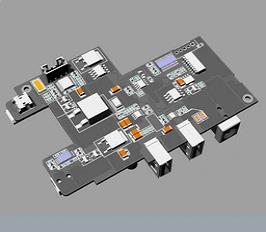
The package using vinyl refers to the COB (Chip On Board) package.
The COB packaging process is as follows:
The first step: crystal expansion. The expansion machine is used to uniformly expand the entire LED chip film provided by the manufacturer, so that the tightly arranged LED die attached to the surface of the film is pulled apart to facilitate the thorn crystal.
Step 2: Adhesive. Place the expanded crystal ring on the backing machine surface where the silver paste layer has been scraped, and put the silver paste on the back. Some silver paste. Suitable for bulk LED chips. Use a dispensing machine to spot an appropriate amount of silver paste on the PCB printed circuit board.
The third step: Put the crystal expansion ring prepared with silver paste into the piercing crystal holder, and the operator will pierce the LED chip on the PCB printed circuit board with a piercing pen under the microscope.
Step 4: Put the pierced PCB printed circuit board in a thermal cycle oven at a constant temperature for a period of time, and take it out after the silver paste has solidified (do not leave it for a long time, otherwise the LED chip coating will bake yellow, that is, oxidize, give the bonding Cause difficulties). If there is LED chip bonding, the above steps are required; if there is only IC chip bonding, the above steps are canceled.
The fifth step: stick the chip. Use a dispenser to put an appropriate amount of red glue (or black glue) on the IC position of the PCB printed circuit board, and then use an anti-static device (vacuum suction pen or sub) to correctly place the IC die on the red glue or black glue.
The sixth step: drying. Put the glued die in a thermal cycle oven on a large flat heating plate and let it stand at a constant temperature for a period of time, or it can be cured naturally (for a longer time).
The seventh step: Bonding (playing the line). The aluminum wire bonding machine is used to bridge the chip (LED die or IC chip) with the corresponding pad aluminum wire on the PCB board, that is, the inner lead of the COB is welded.
The eighth step: pre-test. Use special testing tools (different equipment for COB for different purposes, simply high-precision stabilized power supply) to test COB boards, and re-repair the unqualified boards.
Step 9: Dispensing. A glue dispenser is used to place an appropriate amount of the prepared AB glue onto the bonded LED die, and the IC is packaged with black glue, and then packaged in appearance according to customer requirements.
The tenth step: curing. Put the sealed PCB printed circuit board into a thermal cycle oven and let it stand at a constant temperature. Different drying times can be set according to requirements.
The eleventh step: post-test. The packaged PCB printed circuit boards are then tested for electrical performance with special testing tools to distinguish between good and bad.
The twelfth step: polishing. Grind according to the customer's requirements for product thickness (generally soft PCB).
The thirteenth step: cleaning. Clean the product.
The fourteenth step: air dry. Air-dry the cleaned product twice.
Step 15: Test. The success or failure is determined at this step (there is no better way to remedy the bad film).
The sixteenth step: cutting. Cut the large PCB into the size required by the customer
The seventeenth step: packaging and leaving the factory. Pack the product.
The melting point of vinyl is relatively low. When mounting, first encapsulate the wires with vinyl, and then install the chips and other easily damaged originals. Add vinyl once, because the next filling is less vinyl, it is guaranteed The package will not damage the original.

The shell used to install the semiconductor integrated circuit chip plays the role of placing, fixing, sealing, protecting the chip and enhancing the electrothermal performance, and it is also a bridge between the internal world of the chip and the external circuit-the contacts on the chip are connected to the package shell with wires On the pins, these pins establish connections with other devices through wires on the printed board. Therefore, packaging plays an important role in both CPU and other LSI integrated circuits.
The most important ones are epoxy resin and ceramics.
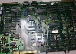
The former is a dual in-line package, and the latter is the most common type of SMD package. As shown in the figure below (marked with N is DIP, marked with D is SOP)--
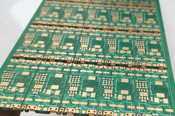
Introduction to Semiconductor Packaging:
The semiconductor production process consists of wafer manufacturing, wafer testing, chip packaging and post-package testing. Semiconductor packaging refers to the process of processing the tested wafers according to the product model and functional requirements to obtain independent chips. The packaging process is: the wafer from the previous wafer process is cut into small chips (Die) after the dicing process, and then the cut chips are attached to the corresponding substrate (lead frame) frame with glue. On the island, use ultra-fine metal (gold, tin, copper, aluminum) wire or conductive resin to connect the bond pad of the chip to the corresponding lead of the substrate to form the required circuit ; Then the independent chip is encapsulated and protected with a plastic shell. After plastic encapsulation, a series of operations are required, such as post-curing (Post Mold Cure), trimming and forming (Trim&Form), plating (Plating), and printing. After the packaging is completed, the finished product is tested, which usually goes through the procedures of Incoming, Test, and Packing, and finally warehousing and shipment. The typical packaging process is: dicing, loading, bonding, plastic packaging, flash removal, electroplating, trimming and molding, appearance inspection, finished product testing, packaging and shipment.
1 Overview of semiconductor device packaging
Electronic products are composed of semiconductor devices (integrated circuits and discrete devices), printed circuit boards, wires, complete machine frames, casings, and displays. The integrated circuits are used to process and control signals. Discrete devices are usually signal amplification and printing. Circuit boards and wires are used to connect signals, the frame shell of the whole machine is used for support and protection, and the display part is used as an interface for communication with people. Therefore, semiconductor devices are the main and important part of electronic products, and have the reputation of "the rice of industry" in the electronics industry.
my country developed and produced its first computer in the 1960s. It occupies an area of about 100 m2 or more. Today's portable computers are only the size of a schoolbag, while future computers may only be the size of a pen or smaller. This rapid reduction in the size of computers and their increasingly powerful functions are a good evidence of the development of semiconductor technology. The credit is mainly due to: (1) The substantial increase in semiconductor chip integration and wafer fabrication (Wafer fabrication) The improvement of the lithography precision has made the function of the chip increasingly powerful and the size smaller; (2) The improvement of the semiconductor packaging technology has greatly increased the density of integrated circuits on the printed circuit board, and the volume of electronic products has been greatly increased. reduce.
The improvement of semiconductor assembly technology (Assembly technology) is mainly reflected in the continuous development of its package type (Package). Usually referred to as assembly (Assembly) can be defined as: the use of film technology and micro-connection technology to connect the semiconductor chip (Chip) and the frame (Leadframe) or substrate (Sulbstrate) or plastic sheet (Film) or the conductor part of the printed circuit board In order to lead out the wiring pins, and fix them by potting and sealing with a plastic insulating medium, forming the process technology of the overall three-dimensional structure. It has the functions of circuit connection, physical support and protection, external field shielding, stress buffering, heat dissipation, oversize and standardization. From the plug-in package in the triode era and the surface mount package in the 1980s to the current module package, system package, etc., predecessors have developed many package forms, and every new package form may require New materials, new processes or new equipment are used.
The driving force driving the continuous development of semiconductor packaging is its price and performance. The end customers of the electronic market can be divided into three categories: home users, industrial users and national users. The biggest feature of home users is that the price is cheap and the performance requirements are not high; national users require high performance and the price is usually tens or even thousands of times that of ordinary users, mainly used in military and aerospace, etc.; industrial users are usually price and performance All fall in between the above two. Low prices require cost reduction on the original basis, so that the less materials used, the better, and the larger the one-time output, the better. High performance requires a long product life and can withstand harsh environments such as high and low temperatures and high humidity. Semiconductor manufacturers are always looking for ways to reduce costs and improve performance. Of course, other factors such as environmental protection requirements and patent issues force them to change the package type.
2 The role of encapsulation
Package (Package) is necessary for the chip, but also very important. Packaging can also be said to refer to the installation of semiconductor integration...The rest of the full text>>
Bound package, commonly known as cow shit, is the cheapest, and it is prone to failure due to moisture.