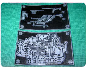
1, Printed board shape processing method
Milling shape. When using a CNC milling machine to process the shape, you need to provide the milling shape data and the corresponding pipe position hole files. These data are provided by the programmer.
Since the printed board jigsaw spacing is unlikely to be very large, generally about 3mm, the milling cutter diameter is generally 3mm. First, drill pipe holes on the milled mattress board, fix the PCB and the milled mattress board with pins, and then mill the shape with the milling shape data; 2 punch the shape.
To use a punch to punch the shape, a mold is required, and the pipe positioning nail on the mold corresponds to the pipe positioning hole of the printed board. Generally, a hole of about φ3.0mm is selected as the pipe positioning hole; 3 "V" grooves are opened. Use a "V" groove cutting machine to cut the printed board into several connected parts along the "V" groove line designed for the printed board; 4-drill shape. Use a drill press to drill holes along the contour line. Usually, the "V" groove and drill shape are only used as auxiliary means for machining.
2, The choice of shape processing method.
The choice of the shape processing method usually depends on the customer's requirements. The shape of the profile is related to the processing batch. Generally, the milling profile is selected. When programming the milling profile data, pay attention to the selection of the lower tool point and the direction of the tool. It is sufficient to ensure that the cutting direction of the effective profile and the cutting direction is 180º.
Therefore, the milling profile is opposite to the direction of the cutting tool in the milling groove. The influence of knife and starting action on the shape; for the same reason, if the inner groove has a convex corner, the lower tool point for milling the inner groove is selected at the convex corner; if the inner groove does not have a convex corner, the lower tool point is selected on both sides of the inner groove It is the radius of the milling cutter.
In addition, when the tool is started at the lower tool point since the right-angle side of the printed board has been milled, the extrusion of the milling cutter on the board during milling will deform the right-angle from shape to shape.
Therefore, when milling the shape, the board Add a rounded corner with a radius of 0.8mm to the four corners to make the right-angle shape into shape. When it is not possible to add pipe position holes in the printed board unit, add pipe position holes on the side of the jigsaw board, add lifting points between the printed board units, and after milling the shape, use a file to remove the lifting points. The punching profile can meet the needs of mass production, and the processing efficiency is high. Generally, the selection of the pipe position hole has a greater impact on the quality of the profile processing and the processing efficiency.

3, "V" groove and drill shape are very effective auxiliary means for shape processing.
Among them, the "V" groove is a more commonly used auxiliary method for contour processing. When the size of the printed board unit is small, in order to reduce the milling time, several printed boards can be assembled into one unit, and the "V" groove can be opened after the shape is milled. This not only improves the efficiency of shape processing but also benefits Plate cleaning and product packaging have also improved the utilization rate of the sheet material. For printed boards with smaller dimensions that cannot be added with pipe positions, the number of lifting points can be reduced (it is very troublesome to file the lifting points). Larger batches of panels are very advantageous.
When the customer requires crafting edges or a variety of board patterns and putting them together, opening the "V" groove is the preferred shape processing method. Although opening the "V" groove has the advantage of high efficiency, due to the equipment (only refers to our "V" groove cutting machine), the distance between the "V" grooves cannot be too large, and the "V" groove cannot be opened along the fold line.
Compared with this, although the drill profile is slower, it can overcome the above difficulties and also overcome the shortcomings of the larger diameter of the milling profile. Adding stamp holes between the unit panels (a series of holes with a distance between adjacent holes greater than about 0.2-0.5mm in diameter, and a hole diameter of less than 1.0mm) can meet customer requirements; there are also customers who cannot open multiple boards together. When the "V" slot is used, stamp holes can be added in the printing room (such as printed board A and printed board B). If the printed board has an inner gap with a width d less than the diameter of the milling cutter, it cannot be processed by a milling profile. It can be achieved by drilling multiple times. When milling the outline, only the outer frame is milled.
The shadow area of the tangent circle of the object in figure 4 is not processed by the milling cutter. Use drills of different sizes to process by drilling, and then match the milling shape., The contour processing can be completed; the processing method of adding lifting points between the printed boards and filing the lifting points after milling the shape has been introduced.
If stamp holes are added to the ink contour lines of the lifting points, the difficulty of filing the lifting points can be greatly reduced. . There is an inner groove on this board. For example, a 3.0mm milling cutter is used to mill the shape. If the width of the plate groove is less than 8mm, the corresponding inner corner will occupy 3/8 of the brightness. The groove width is 3/16, which reduces the inner circle angle. If the customer is still not satisfied, you can also put the hole less than 1.0mm first, and then put the hole of -φ1.5mm, so that the inner circle angle is less than 0.5mm. The inner circle angle is less than 0.5mm.
4, Placement of the pipe position hole is an important factor in the shape processing.
Punching profile and milling profile are commonly used methods for profile processing. The punch profile processing efficiency is very high, but they are inseparable from the corresponding tube hole. Sometimes the placement of the tube hole has a great impact on the shape processing. Usually, add two pipe position holes in the printed board unit, usually placed on the diagonal of the board. In principle, the farther the distance is, the better the positioning, but for the board with a large difference in length or width, it is generally about 200mm along the edge of the board.
Place a pipe position hole. In addition, for some special shapes, the number of tube location holes may be more than two, and the position may not be on the opposite corner. If there is a process edge in the customer's technical data, the tube location hole is better to be added on the process edge or at the corner of the board. Choose two non-metalized holes with a diameter of 2.0-4.0mm as positioning holes.
The placement of the pipe position holes of the punching shape is very important. In order to improve the utilization rate of the mold and the labor productivity, the printed boards with the same shape but different wiring use the same mold. When designing the mold, select a general mounting hole as the pipe position hole. The process side is added to the process side, which often requires full consultation with the customer's technical experts.
Regardless of the punching shape or the milling shape, we like to add pipe position holes in the printed board unit (or choose a certain type of hole as pipe position holes), but unfortunately, some customers do not allow pipe position holes in the board. And it is not possible to select a certain type of hole as the tube position hole in the board, we have to adopt the outer tube position processing shape, that is, add the tube position hole outside the printed board unit.
If the shape of the printed board unit has an internal gap, we can add the tube position hole to the internal gap, and add a stamped hole on one side of the gap to connect to the printed board unit. After milling the shape, break off the small pieces at the inner notch, file to remove the burrs, and the punching shape can also use the same method to add pipe position holes; if there is a hollow groove in the printed board unit, the pipe position hole can be added to the inner groove, The three sides of the inner groove are processed by punching/milling, and the other side is connected with the printed board unit with a stamped hole. After the shape is processed, the small and medium pieces in the groove are removed. If the customer agrees, the center of the stamp hole and the center of the groove can be overlapped.
The file burr process can be eliminated. In order to ensure the internal fillet, the four corners of the groove can be flushed out when punching the shape, and the middle part of one side of the groove is connected with the board through a stamped hole. The other structure is to add a process block to the edge of the board (the process block is superior to the process edge), the process block is connected with the printed board unit with a stamped hole, and the pipe position hole is added to the process block, and the process block is removed after punching/milling the shape., File flat burrs, which can reduce the number of hanging points.
When the punching profile is used for processing, the processing efficiency will be greatly improved, but the addition of process blocks will reduce the utilization rate of the jigsaw. When punching the shape, the general pipe position hole of the mold cannot be added to the board, and the customer does not agree to add the stamp hole, the outside of the board is missing, and the general pipe position hole of the mold is added to the inner groove, and the printed board unit is added Mill out the inner groove or the special pipe position hole that is missing.