With the popularity of computers, Protel's pbc board design is a new circuit-aided design system, a board-level design system that integrates various design tools. The design of pbc board using Protel should generally follow several steps such as determining the shape, layout, wiring, and rule inspection. We sum up some experience and skills in the entire PCB design process from the basic principles of layout and routing.
One, pbc board design quickly determine the PCB shape
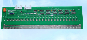
To design a PCB, we must first determine the shape of the circuit board, which is usually to draw the electrical wiring range on the forbidden wiring layer. Unless there are special requirements, the shape of the general circuit board is rectangular, and the aspect ratio is generally 3:2 or 4:3. Before drawing, you can draw two horizontal lines and two vertical lines arbitrarily, and then use the "Set Origin" tool in the "Place Toolbar" to set the end point of a line segment as the origin, that is, the coordinates are (0, 0), and then Double-click each line segment and change the coordinates of its start point and end point accordingly, so that the 4 line segments are connected end to end to form a closed rectangular frame, and the appearance of the circuit board is determined. If you need to adjust the size of the circuit board during the drawing process, just modify the corresponding coordinate value of each line segment. Considering cost, copper wire length, and anti-noise capability, the smaller the size of the circuit board, the better, but if the board size is too small, the heat dissipation will be poor, and adjacent wires will easily cause interference. However, when the size of the circuit board is larger than 200mm*150mm, the mechanical strength of the circuit board should be considered, and fixing holes should be installed appropriately to play a supporting role.

Two, pbc layout
Before starting the layout, you must first load the components through the network table. In this process, you often encounter errors that the network table cannot be fully loaded. It can be divided into two categories: one is that the component cannot be found, and the solution is to confirm the schematic diagram. The package form of the component has been defined in the, and confirmed that the corresponding PCB component library has been added. If you still can’t find the component, you must make a component package yourself; the other type is missing pins, the most common ones are diodes and transistors. The pin is missing. This is because the pins in the schematic diagram are generally letters A, K, E, B, C, while the pins of the PCB components are numbers 1, 2, and 3. The solution is to change the definition of the schematic diagram, or Just change the definition of PCB components to make them consistent. Experienced designers generally build their own PCB component library based on the package shape of the actual component, which is easy to use and not easy to make mistakes.
When laying out, some basic rules must be followed:
(1) Special consideration for special components. The high-frequency components should be as close as possible, and the connection should be as short as possible; the distance between the components with high potential difference should be increased as much as possible; the heavy components should be fixed by brackets; the heating components should be far away from the heat-sensitive components and installed The corresponding heat sink may be placed outside the board; the layout of adjustable components such as potentiometers, adjustable inductance coils, variable capacitors, micro switches, etc. should consider the structural requirements of the whole machine to facilitate adjustment. In short, some special components should be comprehensively considered from the characteristics of the components, the structure of the chassis, the convenience of maintenance and debugging, etc., to ensure a stable and easy-to-use PCB board.
(2) Layout according to circuit function. If there is no special requirement, layout the components according to the component arrangement of the schematic diagram as much as possible. Normally, the signal is input from the left and output from the right, and input from the top and output from the bottom. According to the circuit flow, arrange the position of each functional circuit unit to make the signal flow smoother and keep the direction consistent. In addition, the digital circuit part must be laid out separately from the analog circuit part to reduce interference.
(3) The text label of the silk screen layer. In order to facilitate the installation and maintenance of the circuit, it is generally necessary to print the required logo patterns and text codes on the upper and lower surfaces of the printed board, such as component label and nominal value, component outline shape, manufacturer logo, etc., many beginners The design of the silk screen layer is often omitted, or only the text symbols are placed neatly and beautifully. After the PCB board is actually made, the characters on the board are either blocked by the components or invaded the soldering area and erased, and some components are labeled Hit on adjacent components, causing inconvenience in assembly and maintenance. The correct layout of characters on the silk screen layer should be unambiguous, straightforward, and beautiful.
Three, pbc board wiring
This is a very important link in PCB design. PCB wiring includes single-sided wiring, double-sided wiring and multilayer wiring. There are two ways of wiring: automatic wiring and interactive wiring. Pay attention to the following issues during the wiring process:
(1) Line length. The copper wire should be as short as possible, especially in high-frequency circuits. The corners of the copper wire should be rounded or beveled. Right or sharp corners will affect the electrical performance in the case of high-frequency circuits and high wiring density. In addition, when double-sided wiring, the wires on both sides should be perpendicular to each other, obliquely crossed or bent to avoid parallel to each other to reduce parasitic capacitance.
(2) Line width. The width of the copper-clad wire should be based on the criterion that can meet the requirements of electrical characteristics and is easy to produce. Its minimum value depends on the current flowing through it, but generally should not be less than 0.2mm. If the board area is large enough, the width of the copper-clad wire is the best Do not be less than 0.3mm. The relationship between the ground wire and the power wire is: ground wire>power wire>signal wire, usually the width of the power wire is 1.2-2.5mm, and the width of the signal wire is 0.2-0.3mm.
(3) Line spacing. The spacing between adjacent copper-clad wires should meet electrical safety requirements. At the same time, for ease of production, the spacing should be as wide as possible. The minimum spacing can at least withstand the peak value of the applied voltage. Generally, the distance between the copper wires between the 2000V potential difference should be greater than 2mm. In the case of low wiring density, the spacing should be as large as possible. Generally, the line spacing should not be less than 0.3 mm.
(4) Shielding and grounding. The common ground wire of the copper-clad wire should be placed on the edge of the circuit board as much as possible. Keep as much copper foil as the ground wire on the circuit board, so that the shielding ability can be enhanced.
PCB board design is a complex and simple process. Even circuits with the same parameters will produce different results because of the PCB component layout design and the direction of electrical wiring.