ESD, this is what we usually call electrostatic discharge (Electro-Stac discharge). From the knowledge we have learned, we can know that static electricity is a natural phenomenon, usually through contact, friction, electric induction, etc. It is characterized by long-term accumulation and high voltage (can generate thousands of volts or even tens of thousands of volts). Volt static electricity), low power, small current and short-term characteristics. For electronic products, if the ESD design is improper, PCB layout design will be carried out, which usually leads to unstable operation of electrical and electronic products.
ESD (Electrostatic Discharge) causes damage to electronic products, and the damage includes both sudden damage and potential damage. The so-called sudden damage refers to severe damage to the equipment and loss of function. This damage is usually detected during quality testing during the production process, so the main cost of rework and repairs will be borne by the factory. Potential damage refers to the partial damage of the equipment, the function has not been lost, and can not be found in the production process of the test circuit board, but the product will become unstable, good or bad when using the product, so the product quality is more harmful.

Among these two types of damage, potential failures account for 90%, and sudden failures account for only 10%. In other words, 90% of static damage is undetectable and can only be found with the user's hands. Mobile phones often stall, automatically shut down, poor voice quality, noise, signal time difference, and key errors are related to most static electricity damage. Because of this, electrostatic discharge is considered to be the most potential killer of electronic product quality, and electrostatic protection has become an important part of electronic product quality control. The differences in the stability of domestic and foreign brands of mobile phones also basically reflect the differences in their electrostatic protection and product anti-static design.
It can be seen that the hazard of ESD static electricity cannot be measured, and companies should take full protection to prevent the loss of ESD static electricity.
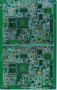
1: Use multilayer PCB as much as possible
Compared with a double-sided PCB, the ground layer and power layer, as well as the tightly arranged signal line-ground spacing, reduce the common mode impedance and inductive coupling, making it 1/10 to 1/100 of the double-sided PCB. Try to shut down each signal layer to the power or ground layer. For high-density PCBs with components on the top and bottom surfaces, short connectors and a lot of floor, please consider using internal cables.
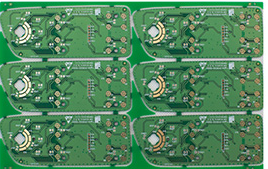
2: For double-sided printed circuit boards, use tightly interwoven power and ground grids.
The power cord should be close to the ground and should be connected between vertical and horizontal lines or filled areas as much as possible. The grid size on one side is less than or equal to 60mm. If possible, the grid size should be less than 13mm.
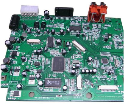
3: Ensure that each circuit is as compact as possible.
4.: Put all the connectors aside as much as possible.
5: Set the same "isolation zone" between the chassis and the circuit grounding on each floor, and keep the interval at 0.64mm as much as possible.
6: When assembling the PCB, do not apply any solder on the top or bottom pads.
Use screws with embedded washers to achieve close contact between the PCB and the metal chassis/shield or ground bracket.
7: If possible, insert the power cord from the center of the card and keep it away from areas that are susceptible to ESD.
8: On all PCB layers that lead to the outside of the chassis under the connector (easy to be directly hit by ESD), place a wide chassis floor or polygonal fillers, and connect them with wells about 13mm apart.
9: Place the mounting hole on the edge of the card. The mounting hole should be connected to the top and bottom pads without solder mask to the periphery of the chassis.
10: At the top and bottom of the card, near the mounting holes, connect the chassis ground and the circuit with a 1.27mm wide wire that is grounded along the chassis every 100mm. Near these connection points, place a pad or mounting hole between the chassis and the circuit location for installation. These ground connections can be pulled out with a blade to keep them disconnected, or they can be bounced with magnetic beads/high-frequency capacitors.
11: If the circuit board will not be placed in a metal chassis or shielded device, the ground wires of the top and bottom chassis of the circuit board cannot be coated with flux, so they can act as electrode arcs for ESD.