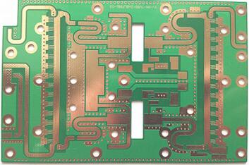
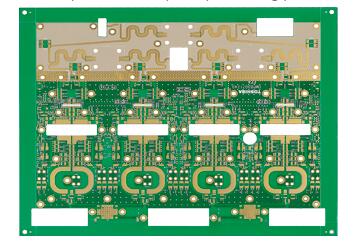
PTFE Multilayer Board as a representative of low loss PCB material, has been in the military and civilian communication field has more than ten years of practical application experience, but by the application scenario and its processability constraints, traditional PTFE PCB with the single, double panel in passive products mainly application, such as base station antenna feed network. But for future millimeter-wave applications, the ordinary single and double panel structure is difficult to meet the design needs, then it can be foreseen for PTFE multilayer board (rather than PTFE+FR-4 hybrid plate) demand will be more and more. At the same time, the emergence of multilayer plate structure makes the number of PTH with signal transmission function is also increasing, which is unavoidable to mention the problem of PTFE multilayer separation.
1., Definition and determination criteria of interlayer separation defects
Internal Connection Defects refers to the presence of non-conductive inclusions between the inner layer copper foil and electroplated copper in the inner wall of the hole, and the inclusions are mainly the drilling dirt produced by drilling during PCB processing. It should be noted that this defect is prevalent in all PCB multilayers, not just PTFE PCB multilayers.
According to the interpretation of the standard IPC-6018B of the printed circuit board industry for the high-frequency plate, to determine whether the interlayer separation defects in The PTFE multilayer board can be accepted, in addition to the initial judgment from the vertical grinding slice, it is also necessary to determine the flat grinding slice to determine whether the residual inclusion is more than 120O, the specific interpretation of the original text as follows:

2, Mechanism of interlayer separation defects in PTFE multilayer board
Compared with ordinary epoxy resin system materials and hydrocarbon resin system materials, PTFE resin system materials are more likely to produce interlayer separation defects when processing multilayer plates, which is mainly due to the characteristics of PTFE resin in the material itself. First of all, PTFE is a thermoplastic resin, and the molecular chain is long and not easy to bend, at high temperature (> 327C) melting will occur; Secondly, PTFE (PTFE) resin as the "king of plastics" has excellent chemical resistance, for the vast majority of chemicals and solvents, inert, strong acid strong alkali, water and a variety of organic solvents.
Although the above two points can be regarded as the unique advantages of PTFE resin, the second processing is the "pain point". In the actual PCB processing process, the high-speed rotation of the drill bit will generate a large amount of heat in the process of contacting the PTFE material, and the heat will melt the PTFE resin in the material and adhere to the drill bit. When the drilling knife is rewound, when the partially melted resin comes into contact with the inner copper foil, the temperature is quickly diverted by the inner copper foil. When the molten PTFE resin is cooled, it is attached to the inner copper layer, forming a residue containing PTFE resin (drilling dirt), and the subsequent chemical (to drilling dirt liquid) or physical (Plasma) to drilling dirt process and almost take PTFE resin "helpless", eventually this residual drilling dirt on the inner copper layer in the copper plating cambium separation defects.

Diagram of interlayer separation defects in PTFE multilayer plates
3, Improvement direction of interlayer separation defects of PTFE multilayer board
For PCB manufacturers who have processed PTFE multilayer board, most of them have experienced the "pain" caused by the defect of interlayer separation. Liquid gas cooling of the bit or the plate to be drilled from time to time has also been proposed to address this defect, or the use of some "special" strong oxidation solution to remove the PTFE residue sticking to the inner copper. However, it is a pity that the above methods have little effect from the perspective of practicability (operability) and practical effect, and do not have the significance of large-scale industrial promotion.
In the author's opinion, the joint efforts of the PTFE material manufacturer (material selection guidance), PCB board factory (process optimization), and the end customer (standard formulation and acceptance) are needed to improve the interlayer separation problem.
3.1 correct material selection
In the author and PCB board factory or OEM engineers on THE PTFE multilayer board communication, will first receive the negative sound for PTFE production of multilayer board, but with the in-depth exchange, found that customers for PTFE multilayer board understanding mostly still stays in more than 10 years ago the traditional PTFE core board material (or called the last generation of PTFE core board material, For example, TACONIC TLY 5, TLX-8, RF-35, etc.), which is characterized by (1) high PTFE resin content (resin content up to wT.75%); (2) containing coarse glass fiber (such as 7628 glass fiber); (3) Low filler content (or no filler), and the use of the previous generation of PTFE core plate material to process the multilayer plate, is bound to appear serious interlayer separation defects.
For the last generation of PTFE core board materials, TACONIC in recent years has successfully launched to the market for PTFE multilayer plate core board materials, such as TSM-DS3, EZIO-28. These two new generations of PTFE core plate materials suitable for the production of multilayer board are characterized by (1) high filler content (wT. 75% +) and high sphericity of the filler; (2) fine glass fiber cloth (e.g. 106,104); (3) Can be matched with very low roughness of copper foil. If suitable materials can be selected for PTFE multilayer processing from the initial selection stage, it will greatly improve the effectiveness of the PCB process on the improvement of interlayer separation.

Multilayer board slice diagram
3.2 optimization of PCB machining parameters
For PCB processes, special attention should be paid to the optimization of drilling parameters, and emphasis should be placed on finding a balance between quality improvement and cost.
(1) Selection of drilling tool: select the optimized tool for PTFE material, especially the tool with excellent chip removal performance. In the design concept of the bit, there are two main design parameters for the chip removal capability: helix Angle and core thickness. The larger the spiral Angle, the thinner the core thickness, the larger the chip slot of the drill bit, the stronger the chip removal ability, at this point, the PCB board factory and drilling tool supplier cooperation is particularly important;
(2) Control of the number of stacks. No matter how thick the PCB to be processed is, drilling is done one by one, and epoxy resin or cold punching plate is used as the cover plate up and down;
(3) Control of the maximum number of holes (it is recommended to change the tool for less than 200 holes). This is the control point that contributes the most to the improvement of interlayer separation in THE PCB manufacturing process, but it is also the link that contributes the most to the drilling processing cost, which requires PCB board factories to find a balance point.
(4) Suitable drilling parameters. According to TACONIC's experience, relatively low rotational speed and feed rate are more beneficial to reduce drilling dirt than high rotational speed and fast feed, thus improving the interlayer separation defects.
3.3 Formulation of accepted standards for end-customers (OEM)

Multilayer board slice diagram
So far, in the military-to-civilian communications market, the PTFE composite board is not in the true sense of the application of large scale, in addition to the current standard of IPC, most of the OEM of the request the separation between the layers are extended to conventional FR-4 professional acceptance criteria, but the author thinks that due to the digital system board and microwave radio frequency board assembly and application environment are different, Therefore, the traditional acceptance standard remains to be discussed. "Zero" risk and "some order of magnitude" risk are not generalizable to the cost of quality.
4., Endnotes
To improve the defect of interlayer separation of PTFE multilayer board, material selection, PCB processing, and customer acceptance criteria should be carried out. Systematic thinking is more helpful to promote the improvement of interlayer separation to obtain better improvement results.