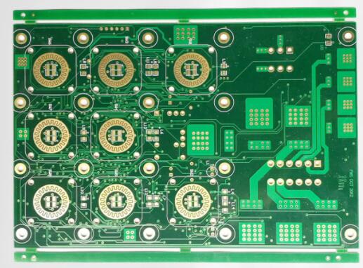
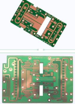
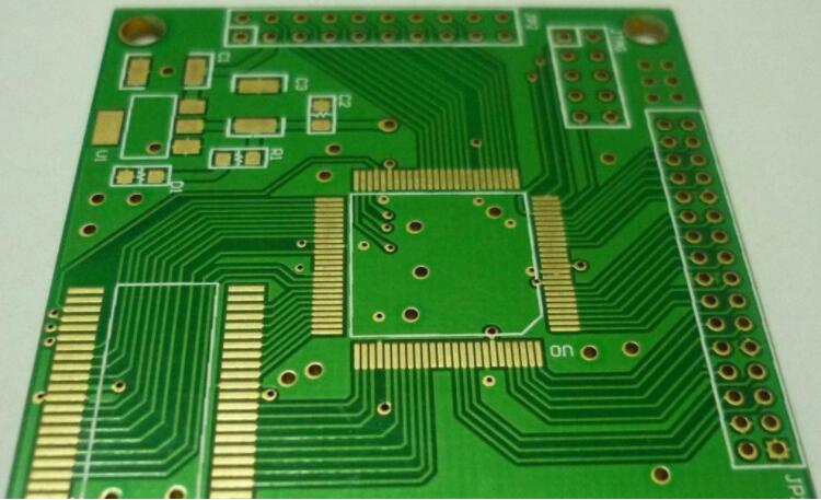
With the development of wireless communication and broadband network, PCB is no longer simply laying metal wires on some insulating substrates to realize interconnection. In many cases, substrates and metal conductors have become part of functional elements. Especially in RF applications, the components interact with the substrate. Therefore, the design and manufacture of PCB have a vital impact on the function of products. As shown in Figure 1 on the left, the conductors on a typical part of the microwave plate are elements.
We PCB manufacturers are also more involved in design related things, especially in high-frequency and high-speed signal transmission. Similarly, designers must have an in-depth understanding of PCB manufacturing process in order to comprehensively produce qualified and high-performance PCB.
Starting from this issue, we will introduce some parameters we often contact, and make some technical discussions from shallow to deep, hoping to deepen the communication and exchange between design and manufacturing.
1. Dielectric constant
Dielectric constant (DK, ε, Er) determines the speed at which the electrical signal propagates in the medium. The speed of electrical signal propagation is inversely proportional to the square root of dielectric constant. The lower the dielectric constant, the faster the signal transmission speed. Let's make an image analogy. I just want you to run on the beach. The water depth drowns your ankles. The viscosity of water is the dielectric constant. The more viscous the water is, the higher the dielectric constant is, and the slower you run.
Dielectric constant is not very easy to measure or define. It is not only related to the characteristics of the medium itself, but also related to the test method, test frequency, material state before and during the test. The dielectric constant will also change with the change of temperature. The temperature factor is taken into account in the development of some special materials. Humidity is also an important factor affecting the dielectric constant, because the dielectric constant of water is 70, and little water will cause significant changes
The following are the dielectric constants of some typical materials (at 1MHz):

Dielectric constant of material
It can be seen that for high-speed and high-frequency applications, the most ideal material is the air medium wrapped by copper foil, and the thickness tolerance is + / - 0.00001 ". As a material development, everyone is working in this direction. For example, the foamclad developed by Arlon patent is very suitable for the application of base station antenna. However, not all designs are based on the fact that the smaller the dielectric constant is, the better. It often depends on some actual designs. Some circuits requiring very small volume often require materials with high dielectric constant, such as Arlon's AR1000, which is used in miniaturized circuit design. Some designs, such as power amplifiers, commonly use dielectric constant of 2.55 (such as Arlon diclad527, ad255, etc.) or dielectric constant of 3.5 (such as AD350, 25N / FR, etc.) There are also those with a dielectric constant of 4.5 (such as ad450), which are mainly changed from FR-4 design to high-frequency application, and hope to use the previous design
In addition to directly affecting the transmission speed of the signal, the dielectric constant also determines the characteristic impedance to a great extent. In different parts, the characteristic impedance matching is particularly important in microwave communication. If there is impedance mismatch, the impedance mismatch is also called VSWR (standing wave ratio)
.
Cter: because the dielectric constant changes with temperature, and the materials used in microwave applications are often in outdoor and even space environment, cter (coefficient of thermal of ER) is also a key parameter. Some PTFE filled with ceramic powder can have very good characteristics, such as CLTE
2. Loss, loss tangent, DF, dispersion factor
In addition to dielectric constant, loss factor is an important parameter affecting the electrical characteristics of materials. Dielectric loss is also known as loss tangent, loss factor, etc. It refers to the loss of signal in the medium, or energy loss. This is because when high-frequency signals (they constantly change between positive and negative phases) pass through the dielectric layer, the molecules in the medium try to orient according to these electromagnetic signals, although in fact, Because these molecules are cross-linked and can not be truly oriented, but the change of frequency makes the molecules move constantly, producing a lot of heat, resulting in energy loss. Some materials, such as PTFE molecules, are nonpolar, so they will not be affected by the electromagnetic field, and the loss is small. Similarly, the loss factor is also related to frequency and test methods. The general law is that the higher the frequency, the greater the loss
The most intuitive example is the power consumption in transmission. If the circuit design loss is small, the battery life can be significantly increased; When receiving the signal, the lossy material is used to increase the sensitivity of the antenna to the signal and make the signal clearer
The commonly used FR4 epoxy resin (dk4.5) has relatively strong polarity. At 1GHz, the loss is about 0.025, while the loss of PTFE substrate (dk2.17) is 0.0009. Compared with glass filled polyimide, quartz filled polyimide not only has low dielectric constant, but also has low loss, because the content of silicon is pure.