The current devices are developing in the direction of high speed, low power consumption, small size and high anti-interference. PCB design is an important stage of electronic product design. It can realize the connection and function between electronic components, and it is also an important part of power supply circuit design. High-frequency circuits have higher integration and higher layout density, so how to make the layout more reasonable and scientific for high-speed and high-density motherboards is very important.
High-speed PCB layout design considerations
When designing electrical schematic diagrams, multiple functional module boards should be used according to structural requirements and functional division, and the physical size and installation method of each functional board PCB should be determined. The convenience of debugging and maintenance, shielding, heat dissipation and EMI performance should also be considered.
When planning the layout, you need to determine the layout plan, such as key circuits, signal lines, details of the wiring method, and wiring principles to be followed. Through the inspection, analysis and modification of several steps in the PCB design process. And after the entire layout process is completed, it is no problem to check the comprehensive rules before further design.
About multi-layer PCB layout design:
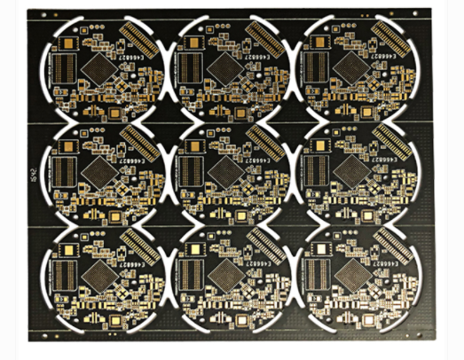
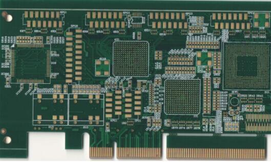
High-frequency circuits are usually highly integrated and have a high-density wiring design. Therefore, the use of multi-layer boards is mainly a necessary and effective means to reduce interference. In the PCB layout stage, it is necessary to reasonably plan the size and number of layers of the board, so that the intermediate layer can be fully utilized for design, which can not only perform grounding treatment, effectively reduce parasitic inductance, shorten the signal transmission length, but also greatly reduce the signal and other factors. Cross-interference and other benefits, the above methods are conducive to the reliability design of high-frequency circuits. Even if the same sheet material is used, the noise of the four-layer board is 20dB lower than that of the double-sided board. However, there is also a problem, that is, the more PCB layers, the more complex the manufacturing process, and the higher the cost. This requires that in the PCB layout, in addition to selecting the appropriate number of PCB layers, a reasonable component layout should also be carried out. Plan and use appropriate wiring rules to complete the design. The following eight points are elaborated around the design of multilayer PCB layout:
Multi-layer PCB layout design
1. The fewer cross-leads of pins between high-frequency circuit layers, the better.
This means that the less Via used in the connection, the better. The reason is that Via can bring about 0.5pF distributed capacitance, and reducing the number of Via can increase the response speed and reduce the possibility of data errors.
2. The shorter the lead between the pins of the high-frequency circuit, the better.
The radiation intensity of the signal is proportional to the wiring length of the signal line. The longer the high-frequency signal wiring, the easier it is to couple to its devices. Therefore, for high-frequency signal lines such as signal clock, crystal oscillator, DDR data, LVDS, USB, and HDMI, the shorter the wiring length, the better, and if there is space, it needs to be packaged.
3. In high-frequency electronic equipment, the smaller the bending of the wiring between the pins, the better.
It is best to use a straight line for high-frequency wire leads. If you need to bend, you can use 45-degree routing or arc routing. This requirement is only used to improve the bonding strength of copper foil in low-frequency circuits, and in high-frequency circuits, meeting this requirement can reduce reflection and coupling interference between high-frequency signals.
4. Pay attention to the "crosstalk" introduced by the signal lines in parallel wiring and close distances.
For high-frequency circuit wiring, attention should be paid to the "crosstalk" introduced by parallel signal lines at close distances. Crosstalk refers to the coupling phenomenon between signal lines that are not directly connected. Since high-frequency signals are transmitted along the transmission line in the form of electromagnetic waves, the signal line will act as an antenna, and the energy of the electromagnetic field will be emitted around the transmission line. Due to the coupling of electromagnetic fields, unwanted noise signals between signals are called crosstalk. The parameters of the PCB layer, the spacing of the signal lines, the electrical characteristics of the transmitting and receiving terminals, and the connection method of the signal lines all have a certain impact on the crosstalk. therefore,

(1) If there is serious crosstalk between two wires, if the wiring space allows, you can insert a ground wire or ground plane between the two wires, which can play a role in isolation and reduce crosstalk.
(2) When the space around the signal line itself has a variable electromagnetic field, if parallel distribution cannot be avoided, a large area "ground" can be set on the other side of the parallel signal line, which can greatly reduce interference.
(3) On the premise of sufficient wiring space, the space between adjacent signal lines can be increased and the parallel length of signal lines can be reduced. The clock line should be perpendicular to the key signal line instead of parallel.
(4) If parallel lines in the same layer are almost inevitable, they must be perpendicular to each other in adjacent layers.
(5) In digital circuits, the usual clock signal is a fast edge change signal, and the external crosstalk is very large. Therefore, in the design, it is recommended that the clock line be grounded and make more space for the ground line to reduce distributed capacitance, thereby reducing crosstalk.
(6) The high-frequency signal clock should use low-voltage differential clock signals as much as possible, and pay attention to the integrity of the perforation.
(7) Do not suspend the empty foot, but ground or connect to the power supply, because the suspension wire may be equivalent to the transmitting antenna, and the grounding can inhibit transmission and so on.
5. High-frequency digital signal ground wire and analog signal ground wire should be isolated.
When connecting the analog ground wire, digital ground wire, etc. to the common ground wire, use high-frequency choke magnetic beads to connect or directly isolate and select the appropriate single-point connection. The high-frequency digital signals of the ground potential of the ground wire are inconsistent, and there is a direct voltage difference between the two, and the high-frequency digital signal ground wire often contains a lot. When directly connected to the digital signal, the high-frequency signal grounded harmonic component signal and the analog signal are grounded. High-frequency signal harmonics will be coupled to the interference of analog signals by way of ground. Therefore, under normal circumstances, the ground wire of the high-frequency digital signal and the ground wire of the analog signal should be isolated to avoid crosstalk between the digital ground and the analog ground.
6. Increase the high-frequency decoupling capacitor of the power supply pin of the IC module.
Add high-frequency decoupling capacitors near the power supply pins of each IC module. Increasing the high-frequency decoupling capacitor of the power supply pin of the IC module can effectively suppress the interference of high-frequency harmonics on the power supply pin.
7. Avoid loops when wiring.
When wiring, various high-frequency signals should not form a loop. If it is unavoidable, the loop area should be as small as possible.
8. The key signal must ensure impedance matching requirements.
In the transmission process, when the impedance does not match, the signal will be reflected in the transmission channel, which will cause the synthesized signal to overshoot, causing the signal to fluctuate near the logic threshold. The basic method to eliminate reflections is to match the impedance of the transmitted signal well. Since the difference between the load impedance and the characteristic impedance of the transmission line is large, and the reflection is large, the characteristic impedance of the signal transmission line should be as equal to the load and impedance as possible. At the same time, it should be noted that the transmission line on the PCB cannot suddenly change or corner, and keep the impedance between the points of the transmission line as continuous as possible, otherwise there will be reflections between each section of the transmission line. This needs to follow the following wiring rules when performing high-speed PCB wiring:
(1) LVDS wiring rules. LVDS signals need to be routed differentially, with a line width of 7 mils and a line spacing of 6 mils.
(2) USB wiring rules. Differential wiring requires USB signals, the line width is 10mil, the line spacing is 6mil, and the ground line and signal line spacing is 6mil;
(3) HDMI wiring rules. HDMI signal differential wiring is required, the line width is 10mil, the line spacing is 6mil, and the spacing between the two sets of HDM1 differential signals exceeds 20mil.
(4) DDR wiring rules. DDR wiring requires signals not to be punched as much as possible. The signal lines have the same width, and the lines are equally spaced. Wiring must comply with the 3W principle to reduce crosstalk between signals.
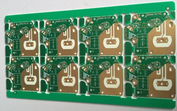
Reduce crosstalk between signals
In addition to the above design methods, high-frequency signals are prone to large electromagnetic radiation when they are routed. Engineers should try to avoid high-speed signal branching or tree stump wiring when wiring the PCB. If the high-frequency signal line is connected between the power supply and the ground, the radiation generated by the electromagnetic wave absorbed by the power supply and the bottom layer will be greatly reduced. In short, high-frequency circuits usually have a high degree of integration and high wiring density. The use of multi-layer boards is a necessary and effective means to reduce interference. In the PCB Layout stage, the size of a certain layer of printed circuit board should be selected reasonably, and the middle layer can be fully used to set the shield, and better achieve close to the ground plane.