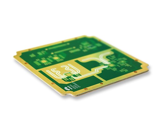
PCB circuit boards are definitely indispensable for mass-produced products. Even amateurs, with a little practice, can make almost perfect, repeatable circuits. Moreover, a printed circuit board with a good ground plane is very important for high-frequency circuits that operate at frequencies exceeding several megahertz. The ground plane is a large-area copper layer that acts as a low-inductance loop between the components in the circuit and the power supply. It can prevent parasitic capacitance from trailing high-frequency signals to form noise. If you lack a ground plane, you don't expect high-frequency circuits made with breadboards to work well, even if they work properly.
But compared with the speed and simplicity of making circuits with breadboards, the use of printed circuit boards to make circuits quickly has disadvantages. You can make your own printed circuit boards quickly-as long as you don't mind the mess and stains on your clothes, and are willing to drill your own. You can also send your own printed circuit board layout to the manufacturer and let them make it for you, but it will take at least a few days and the price is very expensive.

So I began to think about whether there is a viable alternative to make high-frequency circuit boards that are easy to detect and modify. In this article, I only show one of the key concepts; subsequent strategies and methods will be announced on the IEEE Spectrum website in the next few weeks. It should be said that there is no original content here: I just used some techniques that have been forgotten for decades. I didn't expect them to be very effective in the age of working frequencies of up to gigahertz and surface mount components.
Generally speaking, this method first requires a standard circuit board with untreated copper foil, usually FR-4 resin circuit board. Instead of etching the coil, use wires to connect the components, leaving a larger ground plane. I made a "comb generator circuit" as a demonstration.
The comb wave generator circuit can generate a set of harmonics with a wide frequency range and clear boundaries. The frequency I made can reach up to 1 gigahertz. It is a very useful module in a microwave system. The core of the generator is a 74HC00 integrated circuit containing 4 NAND logic gates. The signal generated by the 25 MHz surface mount generator will generate two slightly delayed square wave signals after passing through two NAND gates in series. These signals enter the last NAND gate, producing narrow pulses, forming a harmonic spectrum.
In order to make the circuit, I divided the copper layer into two pieces, intending to make the smaller area at the top serve as a 5 volt power rail, and the rest to form a ground plane.
In order to isolate the two areas, I peeled off three long and thin rectangular copper foils as the boundary of the power rail. First use a scribe to mark the parallel lines; then, close the steel ruler to the parallel line mark, and use a cutter to cut through the copper along the steel rule (requires considerable strength, usually several times to cut through). Finally, heat the copper foil between the parallel lines with a soldering iron, and peel off each piece of copper with tweezers.
The circuit board is usually a single ground plane with no through holes, so how to install an integrated circuit? Bend the ground pin of the integrated circuit back to make it touch the surface, and then place the ground pin in the proper position and solder it to the ground plane. Bend the other pins to make them parallel to the board, and then directly solder the leads to these pins. Since the integrated circuit looks like a bug with its legs stretched out, this method is sometimes called the "dead bug" method. The advantage of this method is that it is easier to access the connection points than using a traditional printed circuit board, and it is easier to solder surface mount components. In addition, there is an area on the ground plane to facilitate connection to the heat sink of the comb wave generator's power regulator.
Continuously cutting and peeling off the strips from the copper-clad layer can form an isolated area in the middle of the board as a connection point between surface mount or through-hole plug-in components. The capacitance between this isolated area and the ground is very small.
Another advantage of this installation method is that it is easy to check whether the high-frequency circuit is indeed operating as designed. Spectrum analyzers with 500ohm resistance probes (such as Tektronix P6056) are very suitable for this type of circuit. You only need to ground the shield of the probe near the test circuit node. After connecting the ground shielding layer of the probe to the upper pogo pin of the grounding shielding layer on the board, I can ground no matter which pin the probe is detecting next to it. (If you can't find a P6056 or similar probe, you can make one yourself: connect a 450 ohm resistor in series with a 50 ohm coaxial cable, but remember to use a 50 ohm terminal on the analyzer side).
The circuit boards produced by these methods are not always very beautiful, but when I use these techniques to make microwave high-frequency circuit boards, I have achieved good results. You can follow me on the Internet to learn more about the above ground plane methods, as well as the skills that my partners and I used in the process of making high-frequency circuits.