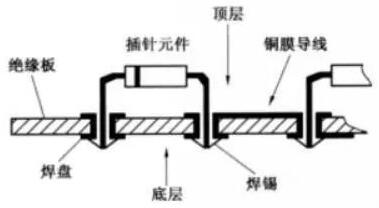
Circuit board socket solder paste reflow
Generally,circuit board manufacturers perform mixed (soldering) technology (Mixed Technology) assembly on the circuit board; that is, the so-called SMT solder paste reflow, plus through-hole wave soldering and other two processes before and after participation. These practices have been practiced for many years, even if they enter the age of lead-free soldering, they can still be manufactured according to the law. The problem is that the heat of lead-free soldering has greatly increased. Even if the front and back are reflowed twice, the plates and components are already in danger. If one more wave of wave soldering is added, the situation is of course even worse. Besides, in addition to large and low-end products, there are fewer and fewer spare parts, so the survival value of wave soldering does have room for review.
At present, the parts that still need to be used for wave soldering are mainly connectors, or larger power or pluggable components, but the number is declining. These structural strength solder joints are still dominated by socket soldering, because their tensile strength is on average 10 times that of SMT. As early as many years ago, in order to save the burden of wave soldering equipment and management, some manufacturers tried a "solder paste hole" method, using hot air reflow instead of wave soldering to complete the soldering of pin sockets and tin filling. . This method is called Pin in Hole (PIH) or Pin in Paste (PIP). It is now becoming popular in the assembly of mobile phone circuit boards. For those who have not installed wave soldering machines, the cost seems reasonable.

1. Prepare in advance
(1) Difference in heat resistance
When changing the original pin wave soldering to solder paste in-hole reflow, the most important concern is whether the part body can withstand the strong heat test of lead-free Reflow without being injured. It should be noted that during wave soldering, although the foot of the bottom part is subjected to intense heat at 270°C for about 4 seconds, the body of the part that is far away from the tin wave through the PCB, does not exceed 160°C even after passing through the two tin waves. As for preheating The top surface in the middle is only 120°C. However, the method of reflow is quite different. Not only must the body of the part be directly exposed to the melting point of 220°C or higher, and suffer from the torture of hot air currents, but the TAL (melting tin duration) is longer than 60 seconds. Therefore, it is known that the heat resistance of PIH components is completely different from that of wave solderers, and must meet the basic requirements of general SMD.
(2) Consideration of the amount of tin filling
In the circuit board manufacturing process, the composition of the solder paste weight ratio is that metal accounts for 88-90%, and the remaining 10-12% is organic auxiliary materials. But the volume ratio is half of each, so that after the completion of healing and condensing into a solder joint, its volume will shrink at least by half. Therefore, the requirement of the amount of tin should be considered when designing the aperture. The general rule of thumb is that the size of the aperture larger than the diameter of the round foot should not exceed 10mi1 (that is, 5mi1 on one side). If it is a square foot, when the thickness measured on the diagonal is compared with the aperture, the difference between the two should not exceed 5mil. Only in this way can the height of the tin in the hole after reflow be able to easily reach the specification of at least 75% of tin in the well-known specification J-STD-001D Table 6-5.
Filling amount
Figure 2. The amount of tin filling in the left picture is acceptable, but in the right picture, only the half-hole dip tin is obviously not up to 75% of the hole length.
(3) The opening of the steel plate.
In order to properly fill the pin holes in the pin holes, the volume of solder paste printed by the squeegee must be large enough. Therefore, the same piece of steel plate must use the method of expanding the over print for this kind of PIH paste. That is, the steel plate must be thicker and the opening must be larger than the hole ring, so the amount of printing paste is barely enough. In fact, thickening of steel plate is not easy to implement for other small pads. On the contrary, for the solder paste expanded beyond the ring surface, there is actually no need to worry about the outward loss, because the strong cohesion in the healing process will pull the amount of tin on the periphery. Back to the center, so there is no need to worry about short circuits after welding.
Dark vision picture of PIH slice
Figure 3. Both images are dark-view images of PIH slices. The insufficient amount of tin in the left image should correspond to the insufficient amount of printing paste.
It is also related to the large gap between the aperture and foot diameter, usually the gap between the two is less than 10mil.
There is also a simple method, that is, there is no need to increase the thickness of the steel plate, as long as the solder paste is printed twice, and with the help of printing expansion, the amount of tin filling in the hole can also be achieved. As for the two-plate superposition printing method of printing a thin paste first and then a thick paste, it is not suitable in terms of cost and construction, but it is quite advantageous for the intensive assembly without any room for expansion. However, it should be noted that after the increase in the amount of solder paste, the residue of the flux will also increase. It will inevitably bring troubles to the visual inspection.
Scratch a piece of steel plate back and forth twice
Figure 4. The same steel plate can be scraped back and forth twice to increase the amount of solder paste printed in the hole.
Lower the angle of attack of the scraper
Figure 5. Lowering the angle of attack of the squeegee (from 60° to 45°> on the left) will increase the amount of paste that enters the hole.
The picture on the right shows that the cutting feet should not be too long, so as not to poke out the solder paste and reduce tin filling and bring other troubles.
2. On-site construction
(1) Cover hole and ring method
This is an early practice. It uses the steel plate opening to cover all the PTH orifices and the ring surface with solder paste, and deliberately lowers the angle of attack of the squeegee or scratches twice to increase the amount of solder paste entering the hole. Then, pierce the pins with round or tapered ends into the holes and then perform reflow. The disadvantage of this method is that the solder paste is often squeezed out or peeled off by too long pins, which brings a lot of trouble. It is best to cut the length of the foot as long as the thickness of the board is slightly more than 50 mils, so that a good solder joint can be obtained.
(2) Hole ring single pass or rain side enlarging method
Deliberately use the expanded opening steel plate for overprinting of a large amount of solder paste (Over P rint), so that the pin reflow can meet the specification requirements of the tin filling amount (75%). At present, the double-sided paste printing method on both sides of the ring is more popular. . Because the hole is not fully covered, there will be no trouble of squeezing out the solder paste from the pin. However, this kind of enlarging technique also needs to signify whether there is enough room on the surface as a construction trade-off.
PIH slice with full tin content
Figure 6. The upper left is the various solder expectations with additional tin, and the lower left is the PIH slice with full tin.
The upper right is the additional forecast posted on the printing paste, and the lower right is the day before the forecast.
(3) Additional anticipation method
Even if the method of double-sided or single-sided expansion is adopted, it is difficult to fill the pin holes with tin to meet the requirements of the specification, so I had to add a small piece of preformed solder preform on the surface of the expanded solder paste. This expectation is a variety of slices punched out of flat solder, completely free of any organic matter, so the volume is very solid, and the effect after soldering is very good (the latest products are also expected to have flux attached). However, due to the limited market, the price is very expensive (a single small piece is charged as much as NT$2), and the automatic placement action is also a headache. In fact, for such thorny issues, as long as the labor is cheap enough and the craftsmanship is good enough, the soldering iron hand soldering method is still the best choice.
PIH is added to the double-sided SMT process
Figure 7. This is the description of adding PIH to the double-sided SMT process, that is, when the top surface is reflowed,
That is, first pin and bend the feet on the top surface, and then turn it over to complete the paste and paste on the bottom surface.
In addition, solder paste was injected into the solder joints, and finally the PIH and the bottom surface were re-soldered at the same time.
(4) Local squeezing method of pin exit (Dispense)
When the front side of the board is reflowed, insert the pins of each interposer into the hole, and bend the tails that pass through. When the flipping of the board executes the solder paste brushing on the reverse side, the robot arm is used to squeeze the paste at a fixed point After the foot tail is put into the furnace, two kinds of reflow can be completed for the insertion and paste of the bottom surface.
Third, the unpopularity is hot again
For the multi-layer boards of mobile phone circuit boards and other hand-held electronic devices, both sides need to be reflowed and soldered with various types of mounting components, but there are a few soldering positions that require better strength (such as charging sockets, etc.). It is still advisable to use through-hole plug welding. For such a small number of needs, of course, it is impossible to make a big fuss and then do another wave soldering. So the PIH or PIP method of solder paste into the hole has become popular recently. The picture on the left below shows the through hole of the OSP processing of the mobile phone board, and the design of the ring on both sides deliberately enlarged.