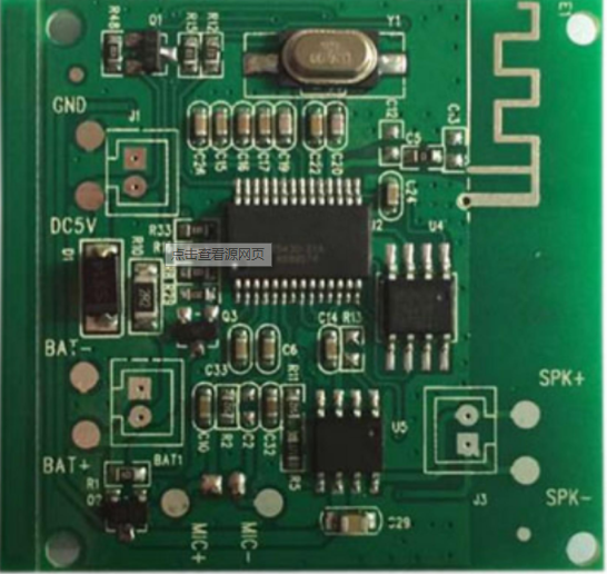
1. Interference between digital circuit module and analog circuit module
If the analog circuit (RF circuit board) and digital circuit work separately, they may work well. However, once they are put on the same RF PCB and work together with the same power supply, the whole system is likely to be unstable.
This is mainly due to the fact that digital signals frequently oscillate between the ground and the positive source (> 3 V), and the period is particularly short, often nanosecond. Due to large amplitude and short switching time. These digital signals contain a large number of high frequency board components independent of the switching frequency. In the analog part, the signal from the wireless tuning loop to the receiving part of the wireless device is generally less than 1 μ v.
Therefore, the difference between digital signal and RF signal can reach 120 dB. Obviously, if we can't separate the digital signal from the RF signal. Weak RF signal may be damaged, as a result, the performance of wireless devices will deteriorate, or even can not work at all.

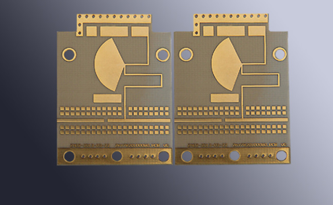
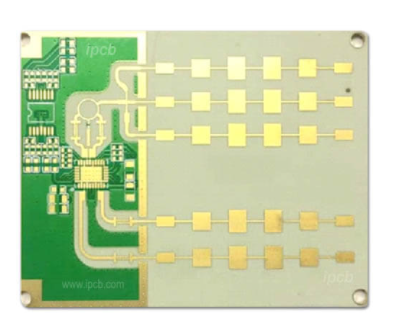
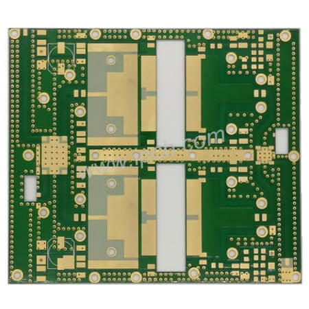
RF circuit design
2. Noise interference of power supply
RF circuit is very sensitive to power noise, especially to burr voltage and other high frequency harmonics. Microcontrollers will suddenly absorb most of the current in a short period of time in each internal clock cycle. This is because modern microcontrollers are made in CMOS technology.
Therefore, suppose a microcontroller operates at an internal clock frequency of lmhz, at which it will extract current from the power supply.
If the power supply is not decoupled properly, it will cause voltage burr on the power line. If the voltage burr reaches the power pin of RF part of the circuit, it may lead to work failure.
3. Unreasonable ground wire
If the ground wire of RF circuit board is not handled properly, some strange phenomena may occur. For digital circuit design, even if there is no ground layer, most digital circuit functions well. In the RF band, even a very short ground wire acts like an inductor.
Roughly calculated, the inductance per millimeter is about lnH, and the inductance of 10 Toni PCB is about 27 Ω at 433 MHz. If the ground layer is not used, most ground wires will be longer and the circuit will not have the design characteristics.
4. Radiation interference of antenna to other analog circuit parts
In PCB circuit design, there are usually other analog circuits on the board.
For example, many circuits have analog to digital converter (ADC) or digital to analog converter (DAC). The high-frequency board signal from the antenna of the RF transmitter may reach the analog input signal of the ADC, and the signal will be sent to the F signal. If the processing of ADC input is unreasonable, RF signal may self excite in ESD diode of ADC input. This leads to ADC bias.