1. Brief introduction of RF PCB design
In a wireless communication system, only a small part of the front-end circuit works in the RF stage, which is commonly known as RF front-end circuit. The rest of the circuit is for low-frequency baseband analog and digital signal processing. Generally, RF front-end circuit includes low noise amplifier, mixer and power amplifier. Although the number of devices in this part of the circuit is much less than that of baseband circuit, it is still the key to the success or failure of the whole system.
Similar to the octagonal rule of Analog IC design, RF PCB design needs analog signal processing in a wide dynamic range and high frequency. Therefore, RF PCB design also has its own hexagon rule. Noise, linearity, power supply voltage, gain, operating frequency and power are the most important indicators in RF PCB. In practical design, any two or more of these parameters will restrain each other, which will lead to a multi-dimensional optimization problem. This kind of compromise selection and mutual restriction poses many problems to the design of RF PCB. It usually requires the intuition and experience of RF designers to get a better compromise scheme.

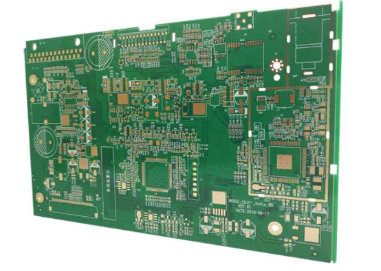
RF PCB design
2. Application fields of RF PCB
(1) Base station RF PCB
(2) Mobile phone RF PCB
(3) Wireless local area network (WLAN) RF PCB
(4) Global positioning system (GPS) RF PCB
(5) Radio frequency tag (RFID) RF PCB
(6) Internet of things (IOT) RF PCB
3. Smith chart
Overview: Smith chart is a special circular chart, which combines characteristic parameters and working parameters into a whole and is solved by graphic method, also known as impedance circle diagram.
Smith chart is widely used in RF microwave amplifier, oscillator, impedance matching and other RF circuit board. It can be used to read the parameters such as impedance, admittance, emission coefficient and standing wave ratio. It can also be used to design LC and transmission line matching circuit boardand analyze the noise figure, circuit gain and stability factor of the circuit.
A typical Smith chart is shown in Figure 1.7 above.

Smith chart is a combination of resistance circle and reactance circle. The upper part of impedance circle is positive, indicating that the impedance is inductive. The lower part X of the impedance circle is negative, indicating that the impedance is capacitive. Any point on the circular graph corresponds to a reflection coefficient and a normalized impedance Z. On the impedance circle diagram, the coordinates (- 1,0) indicate the short circuit point, (1,0) indicate the open circuit board point, and (0,0) indicate the matching point.