1, What is RF circuit board?
Radio frequency is referred to as RF, radio frequency is the radio frequency current board, it is a kind of high frequency alternating current electromagnetic wave abbreviation. Alternating current that changes less than 1000 times per second is called low-frequency current, and that greater than 1000 times is called high-frequency current, and radio frequency is such a high-frequency current.
RF circuit refers to the circuit that processes the electromagnetic wavelength of the signal in the same order of magnitude as the size of the circuit or device. At this time, due to the relationship between the size of the device and the size of the wire, the circuit needs to be dealt with by the theory of distributed parameters. This kind of circuit can be regarded as RF circuit, and there is no strict requirement on its frequency. For example, the long-distance transmission AC transmission line (50 or 60 Hz) sometimes needs to be dealt with by RF theory.
2, Principle and development of RF circuitboard
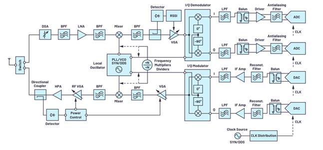
The most important application field of RF circuit is wireless communication. Figure A is the block diagram of a typical wireless communication system. The following takes this system as an example to analyze the role of RF circuit in the whole wireless communication system.

Figure A: block diagram of typical RF system
This is a system model of wireless communication transceiver, which includes transmitter circuit, receiver circuit and communication antenna. This transceiver can be used in personal communication and wireless local area network. In this system, the digital processing part is mainly to process the digital signal, including sampling, compression, coding, etc., and then through the A / D converter into analog form into analog signal circuit unit.
The analog signal circuit is divided into two parts: the transmitting part and the receiving part.
The main function of the transmitting part is: the low-frequency analog signal output from the D-A conversion and the high-frequency carrier provided by the local oscillator are upconverted into radio frequency modulation signals through the mixer, and the radio frequency signals are radiated into the space through the antenna. The main function of the receiving part is: the space radiation signal is coupled to the receiving circuit through the antenna, the received weak signal is amplified by the low noise amplifier, and the local oscillation signal is down converted into the signal containing the IF signal component through the mixer. The function of the filter is to filter out the useful if signal, then input the A / D converter to convert it into digital signal, and then enter the digital processing part for processing.
Next, the composition and characteristics of a general RF circuit will be discussed for the low noise amplifier (LNA) in the block diagram of figure a.
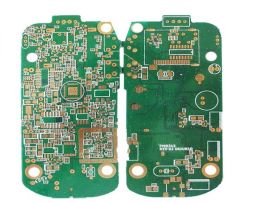
Figure B shows the circuit board diagram of this amplifier, taking tga4506-sm of TriQuint company as an example. Note that the input signal is input to the amplifier module through a matched filter network. In general, the common emitter structure of transistor is used in the amplifier module, and its input impedance must match the output impedance of the filter in front of the low noise amplifier, so as to ensure the best transmission power and minimum reflection coefficient. This matching is necessary for RF circuit design. In addition, the output impedance of the LNA must match with the input impedance of the mixer at the back end, which can ensure that the output signal of the amplifier can be input into the mixer completely and without reflection. These matching networks are composed of microstrip lines and sometimes independent passive devices. However, their electrical characteristics at high frequencies are quite different from those at low frequencies. It can also be seen from the figure that the microstrip line is actually a copper clad strip with a certain length and width, and the microstrip line is connected with sheet resistor, capacitor and inductance.

Figure B tga4506-sm PCB layout
In the theory of electronics, when the current flows through the conductor, the magnetic field will be formed around the conductor; when the alternating current passes through the conductor, the alternating electromagnetic field will be formed around the conductor, which is called electromagnetic wave.
When the frequency of electromagnetic wave is lower than 100kHz, the electromagnetic wave will be absorbed by the surface, and can not form effective transmission. However, when the frequency of electromagnetic wave is higher than 100kHz, the electromagnetic wave can spread in the air and reflect through the ionosphere at the outer edge of the atmosphere to form a long-distance transmission ability. We call the high-frequency electromagnetic wave with long-distance transmission capability as radio frequency. High frequency circuit is basically composed of passive components, active components and passive networks. The frequency characteristics of components used in high frequency circuit are different from those in low frequency circuit. Passive linear components in high frequency circuit are mainly resistor (capacitor), capacitor (capacitor) and inductor (capacitor).
In the field of electronic technology, the characteristics of RF circuit board are different from ordinary low-frequency circuit board. The main reason is that the characteristics of the circuit under high frequency conditions are different from those under low frequency conditions, so we need to use the theory of radio frequency circuit to understand the working principle of radio frequency circuit. At high frequency, stray capacitance and stray inductance have great influence on the circuit. Stray inductance exists in the conductor connection and the internal self inductance of the component itself. Stray capacitance exists between conductors of the circuit and between components and ground. In the low frequency circuit, these stray parameters have little effect on the performance of the circuit. With the increase of frequency, the influence of stray parameters is more and more serious. In the early VHF Band TV receivers, the influence of stray capacitance is so great that it is no longer necessary to add additional capacitors.
In addition, there is skin effect in RF circuit. Unlike direct current, the current flows through the whole conductor under DC condition, while it flows on the conductor surface at high frequency. As a result, the high frequency AC resistance is greater than the DC resistance.
Another problem in high frequency circuit board is the effect of electromagnetic radiation. As the frequency increases, the circuit becomes a radiator when the wavelength is comparable to the circuit size 12. At this time, there will be various coupling effects between circuits, between circuits and external environment, which leads to many interference problems. These problems are often irrelevant at low frequencies.
With the development of communication technology, the frequency of communication equipment is increasing day by day. Radio frequency (RF) and microwave (MW) circuits are widely used in communication systems. The design of high-frequency circuits has been paid special attention by the industry. New semiconductor devices make high-speed digital systems and high-frequency analog systems continue to expand. The carrier frequency of microwave radio frequency identification system (RFID) is 915MHz and 2450MHz; the carrier frequency of global positioning system (GPS) is 1227.60mhz and 1575.42MHz; the RF circuit in personal communication system works at 1.9GHz, and can be integrated into personal communication terminal with smaller size; 4GHz uplink is included in C-band satellite broadcasting communication system Communication link and 6GHz downlink communication link. Usually, the operating frequency of these circuits is above 1GHz, and with the development of communication technology, this trend will continue. However, it needs not only special equipment and devices, but also theoretical knowledge and practical experience that are not used in DC and low frequency circuits.