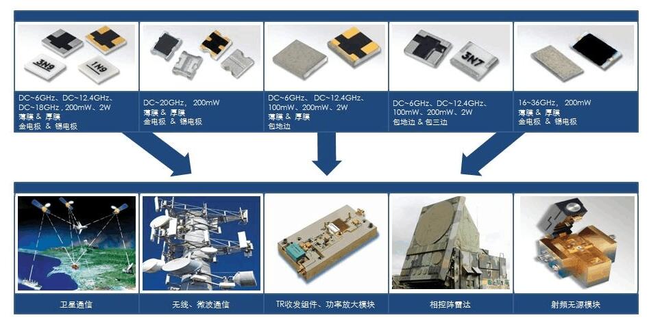
High-frequency PCB board is a key building block for RF/microwave circuits-essentially the starting point for these circuits. PCB materials come in many different forms, and the choice of material is largely dependent on the requirements of the intended application. For example, materials that reliably support high-frequency circuits in commercial wireless products can quickly fail when entering extreme situations in military environments. A basic understanding ofPCB material types and their parameters can help match materials to applications.

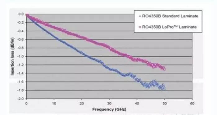
The DK value of the PCB material will affect the size, wavelength and characteristic impedance of the transmission line manufactured on the material. For example, for a given characteristic impedance and wavelength, the size of a transmission line manufactured on a PCB materialwith a high DK value will be much smaller than the size of a transmission line manufactured on a PCB material with a low DK value, although other material parameters may differ. Designers of circuits where loss is a key performance parameter often prefer PCB materials with lower DK values because they have lower loss than materials with higher DK values.
In fact, PCB material can lose signal power in four ways: dielectric loss, conductor loss, leakage loss and radiation loss, although both dielectric loss and conductor loss can be better controlled by the choice of PCB material. For example, the Df parameter provides a way to compare the dielectric losses of different material, where a lower Df value denotes a material with a lower dielectric loss.

For any commercial PCB material, separate CTE values are typically listed for all three axes (X, Y, and Z). CTE provides some evidence of how PCB material handle extreme temperatures, for example during welding. For example, the CTE values of materials used in multilayer structures do not match, which can cause reliability problems because the dimensions of different circuit layers change with temperature. It is generally considered that PCB material with lower CTE values have stronger thermal stability than those with higher CTE values. Circuit materials with a CTE of 70 PPM /°C are considered fairly robust for use over a wide temperature range and should be able to cope with extreme temperatures in which circuits are manufactured and assembled.

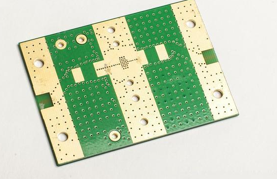
From low-cost FR-4 material to expensive PTFE-based materials, a wide variety of materials are used in RF/ Microwave PCB. The circuit board composed of FR-4 material is essentially a laminate of glass reinforced epoxy resin, while PTFE material is usually reinforced with a glass fiber or ceramic filler (although pure PTFE-based PCB is also used). The difference in performance between these two extreme materials points to the tradeoffs that must be made between the cost and performance of PCB material and between the ease of processing of FR-4 and the difficulty of processing PTFE material.