PCB microstrip receiving antenna applications
Microstrip receiving antenna is a new type of receiving antenna which emerged in the 1970s. As early as 1953, Deschamps proposed the concept of making microstrip receiving antenna by using the radiation principle of microstrip line. It was not until the theoretical plate of microstrip transmission and the development of lithography on copper-coated media substrates that Munson and Howell et al. developed the first batch of practical microstrip receiving antennas. Since the seventies, the microstrip receiving antenna has made further progress in both the breadth and depth of application, and revealed its great potential power in practical application. Various new high-frequency microstripreceiving antennas with new performance and new ways are constantly appearing, and are widely used in satellite communication, navigation remote sensing, weapon control and other military fields, as well as modern mobile communication, private communication, medical components, background care, and other areas used in people's lives.

PCBmicrostripreceiving antenna profile plate
Up to now, in order to obtain their radiation-specific properties more accurately, a variety of physical plates have been developed to mimic high-frequency PCB microstrip receiving antennas. However, no matter which kind of theoretical analysis method is used, they are all trying to solve Maxwell's equations under specially specified boundary conditions, but the methods to deal with specially specified boundary conditions are different, and the specific solutions in the derivation process are different. The proposed physical plate types include transmission line plate, body cavity plate, standard expansion plate, wire mesh plate, radiation aperture plate, etc. These methods complement each other, each has its strengths and weaknesses. The transmission line plate method is suitable for use in most of the engineering applications of the final results, and the calculation is also half large, but the use of this method is limited, only suitable for the analysis of the rule of the rectangular patch. From the point of view of arithmetic, the main methods include transmission line method, cavity mode theory method and vector bit method. From the aspect of digital computing technology, the moment method and finite element method are also used to analyze the microstrip radiation element.
PCB microstrip receiving antenna profile plate
Up to now, in order to obtain their radiation-specific properties more accurately, a variety of physical plates have been developed to mimic high-frequency microstrip receiving antennas. However, no matter which kind of theoretical analysis method is used, they are all trying to solve Maxwell's equations under specially specified boundary conditions, but the methods to deal with specially specified boundary conditions are different, and the specific solutions in the derivation process are different. The proposed physical plate types include transmission line plate, body cavity plate, standard expansion plate, wire mesh plate, radiation aperture plate, etc. Classification of PCB microstrip receiving antennas
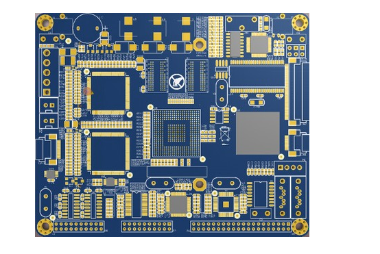
There are many types of microstrip receiving antennas. According to their unique structure, microstrip receiving antennas are generally divided into three types: microstrip patch receiving antenna, microstrip suture receiving antenna and microstrip receiving antenna array (mainly referring to microstrip traveling wave receiving antenna). According to the style classification, there are circular, rectangular, circular microstrip receiving antenna. According to the classification of office principles, it can be divided into resonant (standing wave) and non-resonant (traveling wave) microstrip receiving antennas.
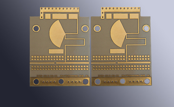
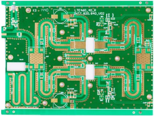
(1) PCB microstrip patch receiving antenna, which is a common microstrip receiving antenna, is composed of a media substrate, a radiation patch and a floor. Radiation patch unit has many styles, whether regular rectangle, polygon, still irregular duck egg round, ring or fan shape, etc., can be used as radiation element. The maximum radiation direction of this kind of microstrip receiving antenna is generally measured in the direction of radiation, that is, straight up to the substrate.
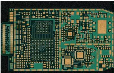
(2) PCB microstrip suture receiving antenna has sutures on the ground floor, so the feeder on the substrate can radiate to one side of the ground floor through sutures under excitation and encouragement. The style of sewing can vary according to the actual situation. It can be divided into narrow slot receiving antenna and wide slot receiving antenna. The microstrip slot receiving antenna can generate radiation on one side of the radiation patch and one side of the floor. Low requirements for manufacturing tolerances; The circular polarization effect can be generated when the microstrip dipole receiver antenna is engaged. It is also a relatively common receiving antenna.
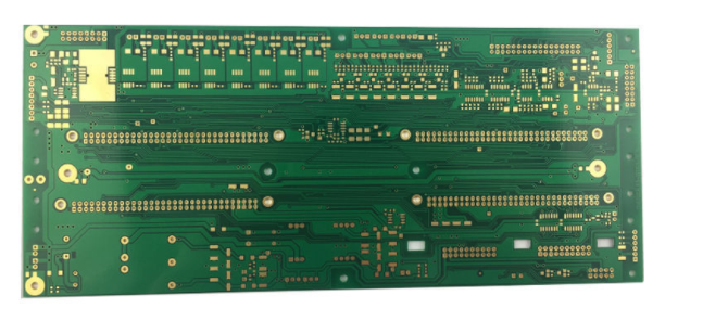
(3) PCB microstrip traveling wave receiving antenna is composed of a substrate, a floor and a series of air radiation pieces. The radiation pieces can be a chain periodic structure or a normal long transmission transmission line of TEM. A microstrip travelling wave receiving antenna can be formed when the terminal is connected with a matched load. The maximum radiation direction of this kind of high frequency PCB microstrip receiving antenna can be located in the arbitrary direction from side to end radiation due to the different presupposition of receiving antenna structure.