This article introduces the PCB design ideas of Rogers RO4003C+ alumina ceramic material realizes millimeter wave functional circuit.
The thin film circuit process of integrated circuits mainly used in the field of microwave and millimeter waves and other high-frequency circuits is the use of vacuum evaporation, sputtering, electroplating, etching and other methods to make conductor wiring, resistors and insulating dielectric films on a polished substrate. It is characterized by high production accuracy, metal line width and spacing can be 10um (correspondingly, the minimum line width and spacing achieved by most PCB manufacturing factories is 100um), and passive components such as resistors, capacitors, inductors, and air bridges can be integrated . The most commonly used substrate materials in thin-film circuits are ceramics, sapphire, quartz, glass, etc. Because of their high dielectric constant and frequency stability, they are very suitable for miniaturized circuits and broadband circuits. PCB with high-frequency PCB as the substrate is used as a carrier for electrical connection of electronic components, not only as a matrix for signal transmission lines (microstrip lines, strip lines, coplanar waveguides, etc.), but also as a carrier for high-density active devices. It can also be combined with thin film circuit technology to introduce thin film circuits into PCB circuits, combining the advantages of the two, and broadening the application range of the circuit. I tried to embed the ceramic substrate made by thin film technology into the microwave circuit board made by the high-frequency board RO4003C to realize the passive device with finer size requirements and enable it to use chip packaged devices.
")
67GHz transmission line parameters (GCPW)
The use of thin film technology on alumina ceramic or quartz substrates can easily realize passive circuit devices (including filters, power dividers, couplers, etc.) in the millimeter wave frequency band, and can produce pad soldering surface mount or flip-chip devices, and Can be reduced in size. Due to the extreme sensitivity to the height difference of the planar circuit in the millimeter wave frequency band, the ceramic and quartz substrates prepared with passive circuit components cannot be directly used on the PCB board, but the sinking method is used on the PCB board, and the PCB board is dug A groove of suitable size and shape (equivalent to a blind hole) is formed, and the bottom of the groove is used as the electrical ground reference surface of the ceramic substrate, and then the ceramic substrate is embedded in the groove, and the fixing method is epoxy conductive adhesive bonding. In this way, I have successfully implemented switching filter components in the frequency range of 35-67GHz, where the filter is implemented on a quartz chip, and the combined input and output signals go through the grounded coplanar waveguide transmission line (GCPW) on the PCB. PCB board material is Rogers board 4003C. The signal connection part of the quartz wafer and the PCB is interconnected by gold wire bonding.
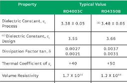
The use of epoxy conductive adhesive to bond alumina ceramic or quartz to the PCB board needs to consider the thermal expansion coefficients of two different materials, otherwise stress damage will occur during the high and low temperature processes. Rogers Sheet 4003C is a sheet widely used in the microwave field. Its X/Y/Z axial thermal expansion coefficients are 11/14/46 (ppm/ degree Celsius) respectively, which is relatively close to alumina ceramics. Good mechanical strength. RO4003C has low dielectric loss (tanδ is about 0.0024), the dielectric constant does not change significantly with temperature and frequency, and the water absorption rate is only 0.04%. These properties ensure that it can be applied to the millimeter wave frequency band. The transmission line adopts the grounded coplanar waveguide form to minimize the influence of the change of the dielectric constant. In the project with the highest frequency to 67GHz, the transmission line parameters are shown in the figure below, and the insertion loss and in-band are measured. The flatness index is more ideal.
In addition, the finished devices made on ceramic substrates (such as mixers, frequency multipliers, etc.) can also be easily applied to the PCB board after sinking. The installation method of the IO mixer is shown in the figure below. The IQ mixer in the figure adopts the ring The oxygen conductive glue is bonded to the groove on the PCB board, and the input and output signals are interconnected by gold wire bonding and the PCB part.

Physical map of ceramic substrate mixer and PCB mounting interconnection
When using a thin-film process dielectric board in a PCB, it is necessary to pay attention to the matching treatment at the high-frequency signal interface. Generally, it is recommended that at the signal connection, the gap between the two media should be kept as short as possible within 0.1mm. Therefore, the slot size accuracy of the PCB board is required.
For rogers ro4003c high frequency PCB material specifications, please view: Rogers RO4003C Data Sheet