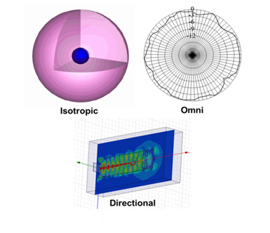
Microwave High-frequency PCB Antennas and high frequency microwave antenna arrays are the "eyes and ears" of all wireless systems. According to the IEEE Standard (145-1983), an antenna can be defined simply as "a device for transmitting and receiving radio waves". The antenna serves as a transducer between the transmitter and free space or between the medium and the receiver. In a broad sense, antennas can be divided into three categories, namely isotropic, omnidirectional and directional. An isotropic antenna is a hypothetical concept of unit gain in all directions. It serves as a benchmark against which actual antenna elements are measured. An omnidirectional antenna is the closest implementation of an isotropic antenna with a nearly constant gain in a reference plane (azimuth or elevation) and is widely used in broadcast applications. Directional antennas, with their high directional gain and narrow radiation pattern (beam), are desirable for applications such as radio detection and ranging (radar) and point-to-point communications.
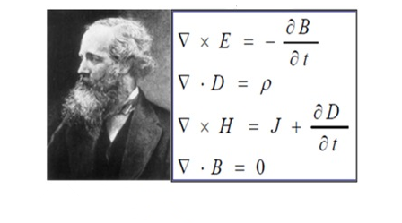
In 1830, Michael Faraday introduced the ring antenna as part of his experiment to study the coupling of electric and magnetic fields. Later, Heinrich Hertz discovered electromagnetic waves and designed dipole antennas. In 1901, Guglielmo Marconi sent messages over the Atlantic using multiple vertical direct ground lines. This is the first use of an microwave antenna array. Maxwell wrote the first collection of papers on EM theory, postulated by Oersted, Faraday, Gauss, and others, and generally known as the Maxwell equation. According to Maxwell, any accelerating charge radiates, so an antenna can be defined as an EM device that controls the flow of a time-varying current. This produces electromagnetic radiation.

The structure of the microwave high-frequency antenna can be considered to have three parts, namely, the electromagnetic generator, the guidance structure and the transition region. The results of finite element method (FEM) simulation of horn antenna show the RF energy flow in the corresponding part. The EM generator feeds the EM wave into the guide structure (the input to the horn) and then directs it to the transition area. The transition region is a matched transformer that matches the impedance of the wire to 377 ohm (free space impedance). EM waves escape from the transition region into free space, thus causing antenna radiation. Although the list of existing antenna types is too large to summarize here, several of them will be selected and discussed based on their commercial and military applications.
High frequency microwave antenna foundation
Antenna Qualification Parameters (AQP)
Antennas can be quantitatively described in terms of spatial and circuit parameters. AQP defines the radiation characteristics and impedance characteristics of the antenna respectively, and they are listed as follows:
1. Antenna gain, G and directivity (directivity gain), D
2. Antenna temperature, T
3. Radiation resistance, R
4. Half power beam width, bandwidth 3dB
5. Direction, observation direction or scanning Angle
6. Side lobe level (SLL) characteristics, such as peak SLL (PSLL), average SLL (ASLL).
7. Cross-polarization (X-Pol) characteristics
8. Axial Ratio (AR)
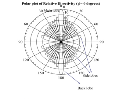
G measures the directionality of the antenna pattern with reference to the isotropic antenna (G = 1), so DBI (for isotropic I) can be measured. It differs from D in that it takes into account various losses in conductors, space (radiation) and conductors (dielectric or air) and is not included in the directional gain D. So G is always less than D. BW 3dB is the angular distance between two -- 3dB points from the maximum or peak value of the main beam in the radiation diagram. The line of sight direction defines the direction in which the main beam of the antenna pattern points when the array is scanned mechanically (using a servomotor) or electronically (by digitally applying a phase shift to the array elements). An ideal high frequency microwave antenna has no side lobes. However, due to the finite nature of the antenna ground plane, due to the phase length and cancellation interference between the current flowing in the forward and reverse directions, the current propagating at the antenna aperture will be reflected from its finite edge, resulting in the formation of side lobes. The sidelobe envelope can be characterized by the PSLL, ASLL and root-mean-square (RMS) SLL with reference to ML measurements. The cross-polarization (X-Pol) level defines the radiation intensity level in a plane that is orthogonal to the desired polarization plane; Therefore, for a horizontally polarized antenna, X-Pol is vertically polarized. The polarization plane defines the plane that contains the electric field vector. AR quantifies the polarization of the antenna. The polarization can be elliptic, circular (AR〜0 dB) or linear (AR〜∞).

Classification of High Frequency Microwave Antenna
It includes wired antennas, traveling wave antennas, reflector antennas, microstrip antennas, log-periodic antennas, aperture antennas, and other antennas such as near field communication (NFC) antennas and fractal antennas. Depending on the type, the gain of a single antenna element may range from 0 dBi (unipolar) to 10-12 dBi (for example, tapered slot antennas and helical antennas). Categories can be selected for certain applications based on specifications such as power handling, G, SLL, size, weight and volume. For example, astronomical radio telescope antennas require very high gain and high power processing capabilities, and require open installation over a large area exposed to different and often severe topological and environmental conditions. These requirements are usually met with reflector antenna arrays. Designed for a plateau with limited real estate, HAPS HAPS 2 Microstrip antennas are useful for fighter jets, light in weight, compact in size, and fit in nature. Traveling wave antennas and log-periodic antennas are useful for ultra-wideband and high power processing applications.
The fractal antenna can be used to realize the embedded antenna structure inside the mobile phone. Planar inverted folding antenna (PIFA) is a good structure for wearable conformal antenna applications. Antenna arrays can be used for applications such as radar, where higher gains are required for detection over a longer range, and directional beams, where target tracking is required.

Microwave high-frequency antenna array can be divided into three broad categories:
Linear antenna array (LAA), consisting of a one-dimensional antenna element cluster. A planar antenna array (PAA), consisting of a two-dimensional cluster of antenna elements. A conformal antenna array (CAA) consists of a conformal array of one - or two-dimensional antenna element clusters arranged on a surface. Samaiyar discussed the application of microwave high-frequency antenna arrays in implementing simultaneous send and receive operations at 5.8GHz in the ISM band. Deep canyons, etc.