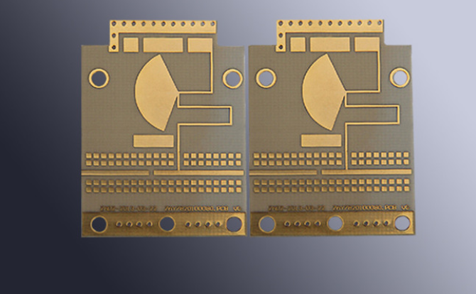
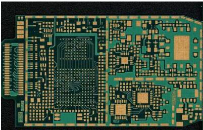
High-Frequency Microwave Printed Board and metal base printed board are the most fashionable technologies and products in the development trend of market economy and high-tech content products.
1. Why is Microwave Printed Board low Dk required?
Dk is called dielectric constant and is the ratio of the capacitance of the electrodes charged with a substance to the capacitance of a vacuum capacitor of the same structure. Usually indicates the capacity of a material to store electrical energy. When ε is large, the storage capacity of electrical energy is large, the transmission speed of electrical signals in the circuit will be below. The direction of the current through the electrical signals on the printed board is usually alternating between positive and negative, which is equivalent to the process of charging and discharging the substrate. In an interchange, capacitance affects transmission speed. This effect is even more important in high-speed transmission devices. DK low means that the storage capacity is small, the charging and discharging process is fast, so that the transmission speed is fast. Therefore, in high-frequency transmission, the dielectric constant is required below.

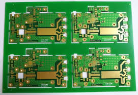
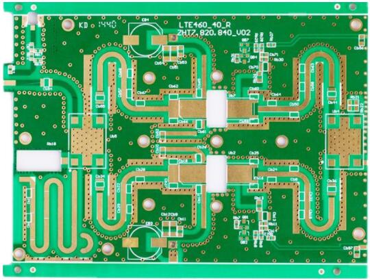
2. Basic requirements for high-frequency microwave printed board
Due to the high-frequency signal transmission, the characteristic impedance of the finished PCB wire is required to be strict, and the line width of the board is usually required to be ±0.02mm (the most strict is ±0.015mm). Therefore, the etching process should be strictly controlled, and the film used for light imaging transfer should be compensated according to the line width and copper foil thickness. The circuitry of this type of printed board transmits high-frequency electrical pulses rather than current. Defects such as pits, gaps, and pinholes in the wires can affect transmission. Any such small defects are not allowed. Sometimes, welding resistance thickness will be strictly controlled, the line welding resistance too thick, too thin a few microns will be judged unqualified.
3. Processing difficulties of high-frequency microwave printed board
Based on the physical and chemical characteristics of polytetrafluoroethylene plate, its processing technology is different from the traditional FR4 process. If it is processed under the same conditions as the conventional epoxy fiberglass copper-clad plate, the qualified product cannot be obtained.
(1) drilling: the substrate is soft, the number of drilling plates is less, usually 0.8mm plate thickness with two pieces of a stack is appropriate; The rotation speed is slower; To use a new bit, the tip Angle of the bit, the thread Angle has its special requirements.
(2) printing resistance welding: after etching, printing resistance welding green oil before the roller brush grinding plate, so as not to damage the substrate. Chemical surface treatment is recommended. To achieve this: no grinding of the plate, printing solder line, and copper surface uniform, no oxide layer, is not easy.
(3) Hot air leveling: Based on the internal performance of fluorine resin, should try to avoid the rapid heating of the plate, tin spray before 150 degree Celsius, about 30 minutes of preheating treatment, and then immediately spray tin. The temperature of the tin cylinder should not exceed 245 degree Celsius, otherwise, the adhesion of the isolated pad will be affected.
(4) milling appearance: fluorine resin soft, ordinary milling cutter appearance burr is very much, uneven, need to suitable special milling cutter shape milling.
(5) transportation between processes: it can not be put vertically, but can only be put flat in the basket. In the whole process, fingers should not be used to touch the line pattern in the PCB board. The whole process to prevent scratches, scratches, line scratches, pinholes, indentation, concave points will affect the signal transmission, the board will reject.
(6) Etching: strictly control the side erosion, serrated, notch, line width tolerance strictly control ±0.02mm. Check with a 100x magnifying glass.
(7) Chemical copper precipitation: the pretreatment of chemical copper precipitation is the most difficult and the most critical step in the manufacture of Teflon plate. There are a variety of methods for copper precipitation pretreatment.
4. Where is the high-frequency microwave PCB used?
Satellite receiver, base antenna, microwave transmission, car telephone, global positioning system, satellite communication, communication equipment adaptor, receiver, signal oscillator, home appliance networking, high-speed computer, oscilloscope, IC test instrument, etc. High-frequency communication, high-speed transmission, high confidentiality, high transmission quality, high memory capacity processing, and other communication and computer fields need high-frequency microwave printed board.
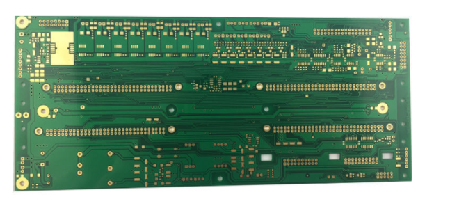
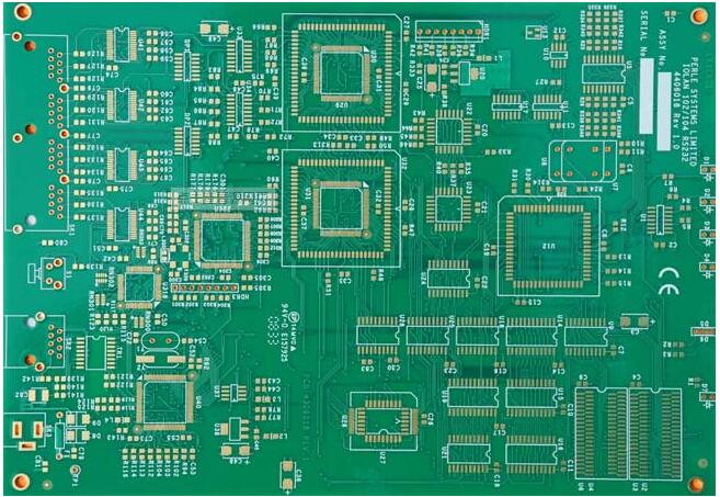
5. Why use metal-based printed boards?
(1) Heat dissipation
At present, many double panels, multi-layer board high density, power, heat distribution is difficult. Conventional PCB substrates such as FR4, CEM3 are bad conductors of heat, layer insulation, heat does not go out. Local heating of electronic equipment is not excluded, leading to high-temperature failure of electronic components, and metal-based printed boards can solve this heat dissipation problem.
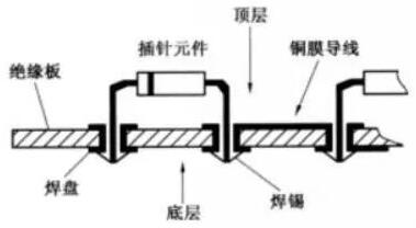
(2) Thermal expansibility
The common nature of substances is that they expand by heat and contract by cold. Different substances have different CTE(Coefficient of thermal expansion).
PCB is a composite of resin + reinforced material (such as glass fiber) + copper foil. The thermal expansion coefficient (CTE) of the printed board was 13~18 PPM/ degree Celsius in the x-y axis direction of the board, and 80~90PPM/ degree Celsius in the z-axis direction of the board thickness, while the CTE of copper was 16.8PPM/ degree Celsius. The CTE of the chip ceramic chip carrier is 6PPM/ degree Celsius. The CTE of the metalized hole wall of the PRINTED board and the connected insulating wall differs greatly on the Z-axis. The generated heat cannot be eliminated in time, and the thermal expansion and cold contraction make the metalized hole crack and disconnect so that the machine and equipment are not reliable.
(3) Dimensional stability
Metal-based printed boards are obviously much more stable in size than insulated printed boards. Aluminum base printed PCB board, aluminum sandwich board, heating from 30 degree Celsius to 140~150 degree Celsius, the size change is 2.5~3.0%.
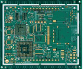
(4) Other reasons
Iron-based printed board with shielding function; Instead of the brittle ceramic substrate; Rest assured to use surface mounting technology; Reduce the actual effective area of a printed board; Replace the radiator and other components, improve the heat resistance and physical properties of the product; Reduce production costs and labor.
High-frequency microwave printed board should be a new variety of high and new technology, with the communication, computer to high frequency PCB and high-speed PCB development, the future use will be more and more widely, more and more large. The plate price is also high, there is a large profit margin, this product has a bright future.