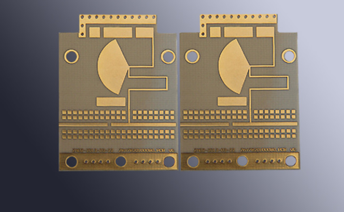
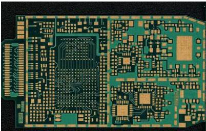
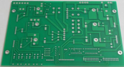
With the development of wireless communication and broadband network, Microwave Printed Boards is no longer simply on some insulating substrate cloth metal wires to achieve interconnection. In many cases, the substrate and metal conductor have become part of the functional element. Especially in rf applications, where components interact with the substrate, PCB design and manufacturing increasingly have a critical impact on product functionality. A typical portion of a microwave hf plate, shown in figure 1 on the left, where the conductors are individual elements.

We PCB makers are also more involved in designing things, especially for high frequency, high-speed signal transmission. Designers must also have a deep understanding of PCB manufacturing processes to produce qualified, high-performance PCBs.
We start from this issue to introduce some of the parameters you often contact, from shallow to deep to do some technical discussion, hoping to deepen the communication and communication between design and manufacturing.
1. Dielectric constant
The dielectric constant (DK, ε, Er) determines the velocity of the electrical signal in the medium. The velocity of the electrical signal is inversely proportional to the square root of the dielectric constant. The lower the dielectric constant, the faster the signal transmission speed. To give you a good metaphor, you're running on the beach and the water is up to your ankles. The viscosity of the water is called permittivity. The stickier the water, the higher the permittivity, the slower you run.
The dielectric constant is not very easy to measure or define, it is not only related to the properties of the medium itself, but also the test method, the test frequency, and the state of the material before and during the test. The dielectric constant also varies with temperature, and some special materials are developed with temperature in mind. Humidity is also an important factor in influencing the dielectric constant, because the dielectric constant of water is 70, and very little moisture can cause significant changes.

It can be seen that the ideal material for high-speed and high-frequency PCB applications is an air medium wrapped in copper foil with a thickness tolerance of +/-0.00001". As a material development, everyone is working in this direction, such as Arlon's patented Foamclad, which is ideal for base station antennas. However, not all designs are the smaller the dielectric constant, the better, it is often based on some practical design, some requirements of the small volume of lines, often need high dielectric constant materials, such as Arlon AR1000 used in miniaturized circuit design. Some designs, such as power amplifiers, commonly use a dielectric constant of 2.55(e.g., Arlon Diclad527, AD255, etc.), or 3.5(e.g., AD350,25N/FR, etc.). There are also those with a 4.5 dielectric constant, such as the AD450, which are mainly switched from the FR-4 design to high-frequency applications, hoping to continue with the previous design.
In addition to directly affecting the transmission speed of the signal, the dielectric constant also determines the characteristic impedance to a large extent, which makes the characteristic impedance matching particularly important in the microwave communication circuit board in different parts. If an impedance mismatch occurs, it is also called VSWR (standing wave ratio).
CTEr: Since the dielectric constant changes with temperature and the materials used in microwave applications are often outdoors, even in the space environment, CTEr(Coefficient of Thermal of Er) is also a key parameter. Some ceramic powder-filled PTFE can have very good properties, such as CLTE.

2. Loss factor (Loss tangent, Df, and Dissipation factor)
In addition to the dielectric constant, the loss factor is an important parameter affecting the electrical properties of materials. Dielectric loss, also known as loss tangent, loss factor, etc., refers to the loss of signal in the medium, can also be said to be the loss of energy. This is because the molecules in the medium try to Orient according to the high-frequency signals (which are constantly shifting between positive and negative phases) as they pass through the dielectric layer, even though they can't really do so because they are cross-linked. But the change in frequency keeps the molecules moving, generating a lot of heat, resulting in a loss of energy. Some materials, such as PTFE, have non-polar molecules, so they will not be affected by electromagnetic field changes, and the loss is small. Similarly, the loss factor is related to the frequency and test method. The general rule is that the higher the frequency, the greater the loss.
The most intuitive example is the consumption of power in transmission. If the circuit design loss is small. Battery life can be significantly increased. When receiving the signal, the loss of the material is used, the antenna's sensitivity to the signal is increased, and the signal is clearer.
The commonly used FR4 epoxy resin (Dk4.5) has relatively strong polarity, with a loss of about 0.025 at 1GHz, while the loss of PTFE substrate (Dk2.17) under this condition is 0.0009. Compared with glass-filled polyimides, quartz-filled polyimides not only have a lower dielectric constant but also a lower loss, because of the pure silicon content.
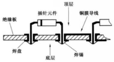
The molecular structure of PTFE is shown in the figure below. We can see that the structure of PTFE is very symmetric, with a tight C-F bond and no polar group. Therefore, with the change of electromagnetic field and the possibility of rocking is very small, shown in the electrical characteristics is a small loss.

3. Thermal expansion Coefficient (CTE)
Thermal expansion coefficient, usually abbreviated as Coefficient Thermal Efficient (CTE), is one of the important thermomechanical properties of materials. Refers to the expansion of material when heated. The actual material expansion refers to the volume change, but due to the characteristics of the substrate, we tend to consider the plane (X-, Y-) and vertical (Z-) expansion respectively.
Planar thermal expansion can often be controlled by reinforced layer materials (e.g., glass cloth, quartz, Thermount), while longitudinal expansion is always difficult to control above the glass conversion temperature.
Flat CTE is essential for installing high-density packages. If the chip (usually CTE between 6-10ppm/C) is installed on a conventional PCB (CTE 18ppm/C), it may cause excessive solder joints to age after multiple thermal cycles. The Z-axis CTE directly affects the reliability of the planting hole, especially for Microwave Printed Boards.