Previously, we shared millimeter-wave communications board deployment scenarios and propagation considerations. Today, we'll look at various beamforming methods: analog, digital, and hybrid. I'm sure you're all familiar with the concept of analog beamforming. Here, we have data converters that convert digital signals to and from broadband baseband or IF signals, connecting radio transceivers that perform up and down-conversion processing. In rf (for example, 28 GHz), we divide a single RF path into multiple paths and perform beam synthesis by controlling the phase of each path to form a beam in the far-field in the direction of the target user. This allows each data path to guide a single beam, so in theory, we could use the architecture to serve one user at a time.
Digital beamforming means what it says. The phase shift is implemented entirely in a digital circuit and is then fed to the antenna array via a transceiver array. Simply put, each transceiver is connected to one antenna element, but in practice, each radio can have multiple antenna elements, depending on the shape of the desired sector. This digital approach enables maximum capacity and flexibility and supports multi-user MIMO development planning at millimeter-wave frequencies, similar to if systems. This is very complex and will consume too much DC power, either in rf or digital circuits, given the technology currently available. However, with the development of future technology, millimeter wave radio will have digital beam synthesis.
The most practical and effective recent beamforming method is hybrid digital-analog beamforming, which essentially combines digital precoding with analog beamforming to produce multiple beams simultaneously in a single space (spatial reuse). By directing power to a target user with a narrow beam, a base station can reuse the same spectrum while serving multiple users in a given time slot. While there are several different approaches to hybrid beamforming reported in the literature, the subarray approach shown here is the most practical implementation, essentially simulating the steps and repetition of beamforming. Currently, the reported system supports two to eight digital streams and can be used to support a single user at the same time or to provide two or more layers of MIMO to a smaller number of users.
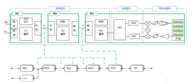
Let's take a closer look at the technical options for analog beamforming, namely building blocks for hybrid beamforming. Here, we divide the analog beamforming system into three modules for processing: digital, bit to millimeter wave, and beamforming. This is not the way a real system is divided, as one would put all millimeter wave components close to reduce losses, but the reason for this division soon becomes apparent.


Various beam synthesis methods
Beamforming capabilities are driven by several factors, including segment shape and distance, power levels, path losses, thermal limits, etc., and are segments of millimeter-wave systems that require some flexibility as the industry learns and matures. Even so, a variety of transmission power levels will continue to be required to address different deployment scenarios, from small cells to macros. Bit to millimeter wave radios for base stations, on the other hand, require much less flexibility and can be largely derived from the current Release 15 specification. In other words, designers can reuse the same radio in combination with multiple beamforming configurations. This is not unlike current cellular radio systems, where small signal segments are common across platforms and the front end of each use case is more customized.
When we move from digital to the antenna, we have mapped the progress of the underlying technologies for the signal chain. Of course, both digital and mixed signals are generated in thin-line CMOS processes. Depending on the base station requirements, the entire signal chain can be developed in CMOS or, more likely, a mix of technologies to provide optimal performance for the signal chain. For example, a common configuration is to use a CMOS data converter with high-performance SiGe BiCMOS IF to millimeter-wave conversion. As shown, beamforming can be achieved using a variety of techniques, depending on the system requirements, which we discuss below. Depending on the selected antenna size and transmission power requirements, a highly integrated silicon approach or a combination of silicon beamforming with discrete PA and LNA can be achieved.

The relationship between transmitter power required for dBm EIRP antenna, antenna size, and semiconductor technology selection
In the previous work, the relationship between transmitter power and technology selection is analyzed, which will not be fully repeated here. However, to summarize this analysis, we include a chart in Figure 3. The choice of power amplifier technology is based on a comprehensive consideration of the required transmitter power, antenna gain (number of elements), and the RF generating capacity of the selected technology. The required EIRP can be achieved with fewer antenna elements using either II-V technology (low integration approach) or a silicon-based high integration approach on the front end. Each approach has its advantages and disadvantages, and the actual implementation depends on engineering trade-offs in terms of scale, weight, DC power, and cost. To generate an EIRP of 60 dBm for the cases derived in Table 1, the analysis conducted by Dr. Thomas Cameron of ADI in his presentation "Architecture and Technology for 5G Millimeter-wave Radio" at the 2018 International Solid-State Circuit Conference concluded that the optimal antenna size is between 128 and 256 elements, Lower quantities are achieved through GaAs power amplifiers, while larger quantities can be achieved using all-silicon beamforming based on RF IC technology.
Now let's look at this from a different Angle. A 60 dBm EIRP is a common EIRP target for FWA, but the value can be higher or lower depending on the expected range of the base station and surrounding environment. As deployment scenarios vary widely, whether, in tree-lined areas, street canyons, or wide-open spaces, there is a significant amount of path loss that needs to be addressed on a case-by-case basis. For example, in a dense urban deployment assumed to be LOS, the EIRP target may be as low as 50 dBm.
The FCC sets defined and published specifications by device category, as well as transmission power limits, and here we follow the 3GPP terminology for base stations. The category of equipment more or less limits the technical choices for power amplifiers.

Various millimeter wave radio size adaptation technology based on transmitter power
While this is not an exact science, we can see that mobile user devices (mobile phones) are well suited to CMOS technology, where the required transmitter power can be achieved with a relatively low number of antennas. This type of radio will need to be highly integrated and power-efficient to meet the needs of portable devices. The requirements for local base stations (small cells) and consumer terminal devices (portable power sources) are similar, involving a range of technologies from low-end CMOS transmitter power requirements to higher-end SiGe BiCMOS. The mid-range base station is well suited to SiGe BiCMOS technology and can achieve a compact overall size. At the high end, for a wide-area base station, a variety of technologies can be applied, depending on the trade-off between antenna size and technology cost. Although SiGe BiCMOS can be applied in the 60 dBm EIRP range, GaAs or GaN power amplifiers are more suitable for a higher power.
a snapshot of current technology, but the industry is making great strides and the technology continues to improve, and improving the DC power efficiency of MMW power amplifiers is one of the major challenges facing designers.
As new technologies and PA architectures emerge, the millimeter-wavecommunications board curve will change and provide a more integrated structure for high-power base stations. Finally, let's review the above points to wrap up the beamforming section - there are no one-size-fits-all, and a variety of front-end designs may be needed to address use cases ranging from small cells to macros.