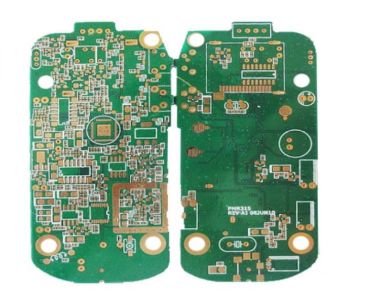
For smart phone high-frequency circuitboard, inductance matching is very important. Inductance matching refers to the signal transmission line so that the output impedance of the circuit at the sending end is consistent with the input impedance of the circuit at the receiving end. After matching, the power at the sending end can be transmitted to the receiving end to the maximum extent.
Matching circuits use capacitors and inductors, but actual capacitors and inductors, unlike ideal components, have losses. The value Q represents the loss. The larger the Q value, the smaller the loss of the capacitor and inductor.
Q value of inductor and loss of high-frequency circuit board
The Q value of the inductor used in the matching circuit also has an effect on the loss of the high-frequency circuit. To confirm this, we used Murata's saw filter (800MHz passband) and RF inductor and measured and compared the insertion loss of the saw filter by changing the RF inductor with different Q values in the matching circuit. Figure 1 shows the circuit diagram. This circuit, though a matching circuit, has only one RF inductor.

Figure 1. SAW filter and matching circuit
Figure 2 shows the frequency characteristics of the Q value of the RF inductor that has been changed this time. Table 1 shows the structure, size, and Q value (Typ at 800MHz. Value)

FIG. 2 comparison of Q values of RF inductance (both 7.5nh)
The diagram in Figure 2 is illustrated using SimSurfing, a design aid provided by Murata.
The overall characteristics of the SAW filter when changing the RF inductorof the matching circuit are shown in Figure 3, and the passband characteristics are shown in Figure 4.

Figure 3. Overall characteristics of SAW filter

Figure 4. Passband characteristics of SAW filter
From the passband characteristics in Figure 4, it can be confirmed that the insertion loss of SAW filters varies depending on the RF inductor used. This level of loss in high-frequency circuit board is becoming increasingly important. According to the experimental results, the larger the Q value of the RF inductor (the smaller the loss), the smaller the insertion loss of the saw filter. In other words, the size of the inductor loss is the size of the SAW filter loss including the matching circuit. Please note that the loss will vary depending on the high-frequency element used (in this case, saw filter), matching circuit, frequency band, etc.
Inductance deviation and the effect on the matching circuit
In addition, the actual inductor impedance values are 1.0nH, 1.1nH, 1.2nH, such as discontinuous values. When matching is done, it is sometimes necessary to fine-tune it with delicate constant steps. At the same time, the deviation of the impedance value (standard deviation) becomes the matching standard deviation, and in order to satisfy the necessary characteristics, an inductor with a small deviation is sometimes required. Among Murata's inductors, the thin film LQP series best meets the requirements of meticulous constant steps and small deviations.
According to the above situation, it is necessary to compare and discuss the Q characteristics, deviation value, size, cost, and other aspects of the integrated loop RF inductor of the saw filter. When the mounting space is left, the coil inductor LQW15/LQW04 with a high Q value is the best choice. In addition, the LQP03HQ/LQP03TN_02 with small size 0603 and smart phone high-frequency circuit board Q value is the best choice when the mounting space is limited.