In the past few years, various types of millimeter-wave circuit have been studied. At the same time, I have been designing circuits in the field of high-speed digital (HSD), but the data obtained from each experiment is always unsatisfactory. In the process of the experiment, the insertion loss curve of some HSD circuits will produce a lot of noise. After several specific experiments, the conclusion is that the return loss of the circuit is very poor. Surprisingly, HSD engineers are also unconcerned with the return loss characteristics of high-speed circuits. Based on experience with millimeter waves, this is incredible, because return loss is one of the key indicators for obtaining valid data. However, with the further understanding of HSD, it is found that the technique is usually applied in the time domain, and the return loss has much less impact on most time-domain problems. With the continuous in-depth research on HSD (especially ultra-high-speed digital vHSD), technology in the field of millimeter-wave can be gradually used to help and improve the related technology and performance of vHSD.
Millimeter-wave impedance conversion is critical for millimeter-wave circuit because good impedance matching results in the circuit achieving the best return loss (a small note: return loss is also commonly referred to as reflection loss, referring to the energy reflected from the propagation medium). For example, impedance mismatches often occur in the transition from the connector to the circuit. If this connection point is not handled well, then the return loss (reflection loss) is too large, and most of the energy intended to be input into the circuit will be reflected. For millimeter-wave circuit, if the test system knows how much energy is going into the circuit and how much is coming out of it, then the insertion loss caused by the circuit itself can be obtained. However, if the index of return loss is poor, it means that most of the insertion loss is not caused by the circuit itself, but by the energy reflected by the circuit. Therefore, the return loss of the circuit is very poor, and the measurement of insertion loss is not accurate.

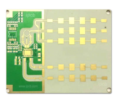
millimeter-wave circuit
Impedance conversion may or may not be a problem for HSD circuits in time-domain signals. It depends on the digital signal rate, the rise time, and the sensitivity of the millimeter-wave circuit. For circuits with relatively slow rise times, impedance conversion has much less effect on digital circuit performance. However, the HSD performance of the circuit may be adversely affected when the rise time is faster and the circuit performance becomes extremely sensitive to subtle exceptions in impedance conversion.
The rate (speed) and rise time of a digital signal are closely related to the characteristics of an analog or rf signal. The simple square wave generated by the clock signal in the HSD circuit is the square wave signal formed by the addition of the RF signal and its higher harmonics. This means that for slower digital speeds, the RF signal used is of relatively low frequency. For example, a 1Gbps digital rate has an analog fundamental frequency of 0.5GHz, followed by 1.5ghz, 2.5ghz, and 3.5ghz harmonics. At these frequencies, the effect of return loss is essentially negligible for most PCB circuits. Therefore, for low frequency and low digital rate circuits, people usually do not pay attention to their impedance transformation and impedance characteristics.
However, for a vHSD circuit with a rate of 28Gbps, it can be seen as a signal composition with analog signals of 14GHz, 42GHz, and 70GHz. At 42Ghz, return loss and associated impedance conversion are very important, and at 70Ghz, they become the primary problem to be solved at the millimeter-wave circuit level. These rf problems can affect vHSD's eye pattern, but in the limited trials, the effect is not as severe as I expected. However, for a sensitive vHSD system transmitting at this rate, return loss and impedance conversion should be fully considered.
Similarly, in high-speed vHSD circuits operating at 56Gbps, the effects of return loss and impedance conversion may affect the performance of the eye map. Therefore, it is strongly recommended that vHSD circuit design engineers have a detailed understanding of millimeter-wave circuit issues and the interconnections between analog and high-speed signals to better optimize high-speed digital circuit design.