Flip chip, as the name suggests, is a packaging method in which the front side of the chip (the side where the IC circuit is made) is connected to the substrate downward. The electrical signal terminals are made of traditional solder and can be interconnected with the substrate. In this type of interconnection, the input and output terminals (I/O) can cover the entire chip, so even at the same pitch, the density of flip-chip interconnection is much higher than that of wire bonding. In wire bond interconnection, I/O can only be arranged around the chip. Therefore, no matter how small the pitch is, the I/O density of flip-chip interconnection cannot be achieved. Then bump technology is the key to the entire flip-chip interconnection technology.
Overview of Wafer Bumping Technology
The key to making wafer bumps is to deposit an under-bump metal layer (UBM). It needs to be pointed out that the term used by IBM in the early days is the ball constrained metallization layer (BLM), which functions as: to provide a bonding layer for interconnection; to provide an atomic diffusion barrier layer to prevent the diffusion of atoms of the bump material to the underlying metal structure; The underlying dielectric material and metal provide an adhesion layer and act as a barrier layer to prevent contaminants from migrating to the underlying metal along the horizontal direction of the dielectric layer.
Most UBMs currently used are made by sputtering processes. The sputtering process is the most cost-effective to make UBM. Especially compared with the evaporation process. The most direct factor that affects the reliability of the solder bump structure is the production quality of UBM. Generally speaking, UBM structures must withstand multiple (often up to 20) reflows without damage. Since UBM is a structure used to bond solder bumps and pad metallization layers together, it must also pass shear stress and tensile stress tests. In mechanical damage testing, the general criterion for solder bump failure is that the failure occurs in the solder itself. Therefore, UBM must have sufficient strength. There will be no performance degradation due to factors such as time, temperature, humidity, and bias voltage.

Flip chip market trends
Flip chip packaging has become the mainstream packaging interconnection technology. So far, flip chip is actually considered a type of packaging, not an interconnect technology. For example, Flip Chip Ball Grid Array Packaging (FCBGA) mainly uses layered substrate technology to complete the assembly and packaging process, but it is limited to high-performance integrated circuit applications.
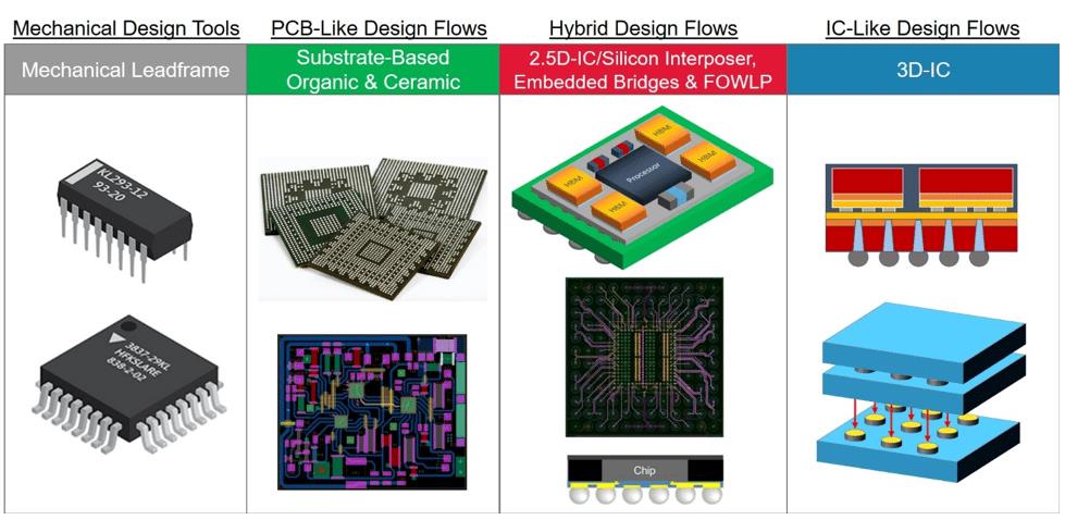
The following figure shows the application areas of flip chip:

(1) Bump pitch: reducing the bump pitch can increase I/O density; the trend of pitch change (gradual transition from 250 microns to 125 microns);
(2) Solder bump sinking method: evaporation-screen printing-electroplating;
(3) Bump solder composition: high lead content-eutectic-lead-free (Sn-Ag)-Cu column pitch<125 microns;
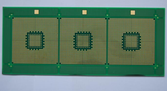
(4) Package composition: ceramic substrate-high-density interconnect laminate substrate-prepreg laminate substrate-low thermal expansion coefficient laminate substrate? Coreless substrate.
(5)Package structure: sealed single-chip cover (SPL)-non-sealed single-chip cover-stiffener + cover-bare chip-molded
The application markets of traditional FCCSP are as follows:
FCCSP application market:
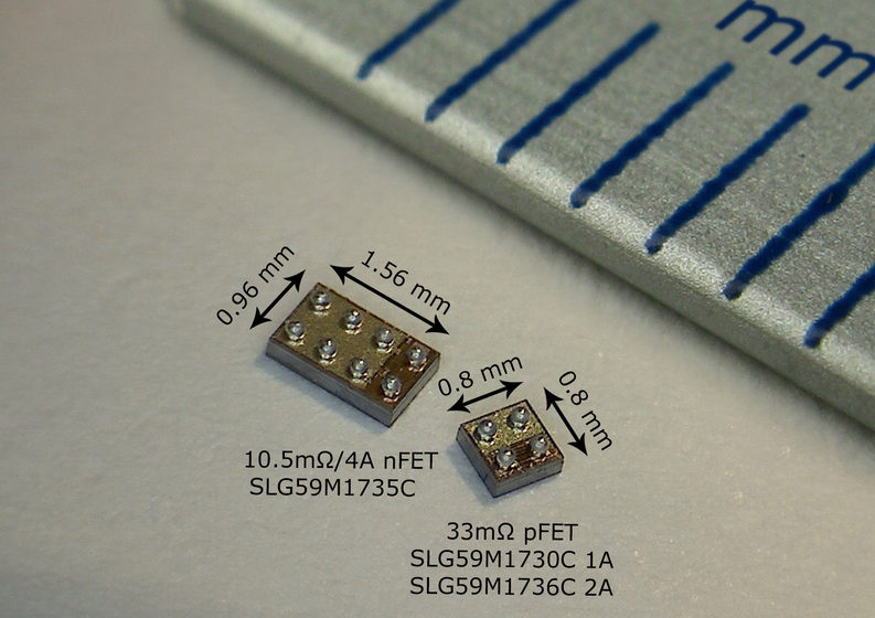
(1) The bump (I/O) density relative to the chip size: used for chip sizes >200 I/O or >5.5mm; lower density products use WLCSP for better and lower cost.
(2) Low power: general power<2w depending="" on="" chip="" board-level="" packaging="" can="" be="" used="" for="" power="" bare="" fccsp="">2W).
(3) Area: For handheld devices, 40nm/65nm technology reduces the chip size, but more I/O makes there is not enough area to arrange the peripheral I/O, so it is necessary to use the substrate lead to fan out the area.
(4) Price: For high-I/O small-size chips, insufficient peripheral area, Au line cost, and large-size substrates for lead fan-out will drive the development of competitively priced FCCSP.
(5) Molding, easy to test and hold, the common form is the same as CABGA.
Summary
Flip chip has always been an exciting packaging technology. But compared to traditional wire bonding packaging, its cost limits flip chip to become the mainstream technology. However, cost constraints are gradually being eliminated, and the use of strip-packaged flip-chips has significantly reduced their costs. Since laminated substrates account for the most product cost, reducing the cost of laminated substrates is the most effective way to reduce the cost of flip-chip packaging.
In addition, for FPFC design, Amkor has conducted a lot of research to transform the existing area array flip-chip design to a fine-pitch design. 80% of the studies found that the fine-pitch peripheral design can reduce the cost of the substrate, which is due to the reduction of the metal layer and the reduction of the external size. By reducing the cost of flip-chip packaging substrates (its cost is the highest), it is possible to make flip-chip packaging widely used in other markets.