The PCB circuit board is widely used in the electronic circuit and IT industry, so the knowledge research on it is a very meaningful subject. So how much do you know about circuit boards? The following is the content of the knowledge about circuit boards organized by the learning editor, I hope everyone likes it!
The circuit boards are divided into three major categories: single-sided boards, double-sided boards, and multilayer circuit boards according to the number of layers.
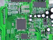
First is a single-sided board. On the most basic PCB, the parts are concentrated on one side, and the wires are concentrated on the other side. Because the wires only appear on one side, this kind of PCB is called a single-sided circuit board. Single-sided panels are usually simple to manufacture and low in cost, but the disadvantage is that they cannot be applied to products that are too complex.

Double-sided board is an extension of single-sided board. When single-layer wiring cannot meet the needs of electronic products, double-sided board should be used. There are copper-clad wires on both sides, and the lines between the two layers can be connected through vias to form the required network connections.
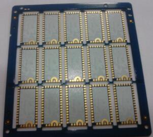
"Multilayer board" refers to a printed board with three or more conductive pattern layers laminated with an insulating material between them, and the conductive patterns are interconnected as required. Multilayer circuit boards are the product of the development of electronic information technology in the direction of high speed, multi-function, large capacity, small volume, thinner and lighter weight.
Circuit boards are divided into flexible boards (FPC), rigid boards (PCB), and rigid-flex boards (FPCB) according to their characteristics.
1, chip with program
1.EPROM chips are generally not suitable for damage. Because this type of chip requires ultraviolet light to erase the program, it will not damage the program during the test. Long), even if it is not used, it may be damaged (mainly referring to the program), so it is necessary to back up as much as possible.
2. EEPROM, SPROM, etc. and RAM chips with batteries are very easy to destroy the program. Whether this type of chip destroys the program after using the
3. For the chip with battery on the circuit board, do not easily remove it from the board.
2. Reset circuit
1. When there is a large-scale integrated circuit on the circuit board to be repaired, pay attention to the reset problem.
2. It is best to put it back on the device before the test, turn it on repeatedly, try the shutdown device, and press the reset button several times.
3, function and parameter test
1. The detection of the device by the
2. Similarly, for TTL digital chips, only high and low output changes can be known, but the rising and falling edge speeds cannot be detected.
4, crystal oscillator
1. Generally, only an oscilloscope (the crystal oscillator needs to be powered) or a frequency meter can be used for testing.
2. The common faults of the crystal oscillator are: a, internal leakage, b, internal open circuit c, degraded frequency deviation d, leakage of external connected capacitors, and current leakage. The VI curve of the tester should be able to be measured.
3. Two judgment methods can be used in the whole board test: a. The surrounding chips near the crystal oscillator failed during the test, b. No other fault points were found except the crystal oscillator.
4. There are two common types of crystal oscillators: a, two pins, b, and four pins. The second pin is for power supply. Be careful not to short-circuit at will.
Five, the distribution of failure phenomena
1. Incomplete statistics of circuit board failure parts: 1) Chip damage 30%, 2) Discrete component damage 30%, 3) Connection (PCB board copper wire) broken 30%, 4) Program damage or loss 10% (Yes Upward trend).
2. It can be seen from the above that when the circuit board to be repaired has a problem with the wiring and the program, and there is no good board, it is not familiar with its wiring, the original program is not found, and the possibility that the board is repaired is unlikely.