With the changes in wireless technology, the number of radio systems in many portable devices continues to increase, and with the emerging Internet of Things and 5G applications, this trend is still growing. This trend has brought challenges to radio frequency designers, because they need to ensure the performance of several radio systems working at the same time, but also need to minimize interference and power loss.
This article explains the problems of multi-system design from the perspective of antennas. The increase in the number of antenna elements in equipment is the main trend in antenna evolution, consistent with the multi-system trend mentioned above. However, antenna diversity, multiple input multiple output and beamforming technology have further promoted this process. At the same time, because the size of the device cannot be increased, the antenna density will increase. This in turn will lead to increased coupling, which is one of the main challenges in the design of multi-antenna systems.
Coupling between antennas
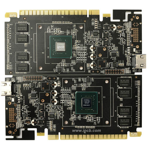
Since antennas are essentially resonant structures, there may be coupling between antennas that are close together. If the distance between the antennas is very close, and their operating frequencies are close to each other, the resonance is stronger. Similar to other physical structures, antennas usually resonate at their lowest frequency or harmonic multiples of the fundamental frequency. Therefore, the antenna suitable for 3GPP band 3 (1710 -1880 MHz) and the 5 GHz antenna (5170-5835 MHz) may have three strong harmonic resonances. The antenna radiation pattern in compact devices is usually isotropic. Although the antenna orientation can be used for isolation through cross-polarization, this approach only works in the simplest cases. For example, in the most ideal case, a dipole pattern with zero radiation along the dipole axis can only isolate three antennas through its pattern properties. The number of peripheral antennas often exceeds the number of antennas located in the near field of each other (Figure 1), and industrial design cannot place the antennas in an optimal electromagnetic positioning manner. Therefore, we have to deal with a certain degree of coupling.
Different radio systems are effectively isolated by the filters of the RF front-end, but there are still multiple reasons, and the coupling effect between the antennas needs to be handled carefully. First, multiple input multiple output systems have the same frequency bands between different types of antennas. Secondly, strong coupling at harmonic frequencies may cause the transmitter A's intermodulation signal to couple to the receiver B's operating frequency band-the filter may also exhibit harmonic periodicity similar to the passband antenna. Third, the filter stop band is usually suitable for 50 ohm circuit environments, and the antenna impedance may be any value other than 50 ohms, causing the actual pass band to deviate significantly from the design value, so the performance is usually better only when the stop band is close to the pass band. This means that the filter of system A may leak the coupled power from system B to system A, resulting in the sensitivity reduction of system A and the power loss of system B. Finally, the radiation efficiency of compact antennas can be very poor. In other words, even if the radio system is completely filtered, the surrounding antennas will consume a large part of the coupling power.
In order to avoid the above problems, we need to propose novel and comprehensive analysis and optimization methods for the antenna system.
Why can't the existing analysis methods cope with it?
In the past, we used three different antenna system analysis methods:
1. Measurement-based method: The S-parameters of the multi-port system are characterized by a multi-port vector network analyzer (VNA), and the radiation pattern corresponding to each antenna is measured by a manual measuring device located in an anechoic chamber.
2. The general radio frequency simulator can analyze the circuit of the antenna system, but has no effect on the radiation-related quantity and efficiency.
3. The electromagnetic simulation system of the antenna system uses a flexible virtual model to replace the manual measurement device, and the conventional electromagnetic software also contains a large amount of analog data post-processing functions.
All the above methods cannot correctly handle the mutual coupling terms in a multi-antenna system. For Method 1, because the radiation efficiency depends on the superposition of the terminal of each port and the 3D radiation pattern, how to correctly calculate the radiation efficiency is also a tricky problem. Moreover, the radiation efficiency data is usually defined by frequency grid points, rather than S-parameters, which may make the total efficiency calculation more complicated. A typical 12-antenna system involves 132 mutual coupling terms. We need to manually write so many coupling terms in the equation to calculate the total efficiency.

Considering the coupling loss and the radiation efficiency related to the terminal at the same time, the electromagnetic simulator is usually more suitable for the multi-antenna problem, and the total efficiency of each antenna can be calculated. Obviously, although the electromagnetic simulator only supports the native project radiation pattern in the native format, unfortunately, there is no standard format for the radiation pattern. This means that in practice, each electromagnetic simulator has its own radiation pattern format, and mode data cannot be shared between different simulators, such as S parameter files.
But electromagnetic simulators also have blind spots. When reaching the antenna port terminal through matching circuits, filters, etc., we need circuit components and their models. The RF simulator pays more attention to the component library, and the actual component model is usually equally important when analyzing the entire system. In addition, this involves not only overall efficiency, but also component losses, voltages and currents connecting different parts of the circuit. When analyzing this type of performance, RF simulators are powerful, but when analyzing overall efficiency, they are undoubtedly unsatisfactory.
All in all, the electromagnetic simulator is suitable for the input from the antenna into the free space, and the radio frequency circuit simulator is suitable for the S matrix port from the amplifier to the characterization of the antenna input. Is there an analytical method that can combine the above two methods?
new method
New software has been developed, which combines the advantages of electromagnetic and radio frequency circuit simulators in analyzing the state of multi-antenna systems, and optimizes system performance through automatic circuit synthesis.
Improving the performance of the antenna system is generally accomplished through relatively simple matching and decoupling circuits. But if you need to ensure that all of the above factors are considered correctly and at the same time, you must correctly characterize the system performance.
The new method has been embedded in the Optenni Lab radio frequency design automation software platform. After years of development, it has been able to seamlessly connect the electromagnetic and circuit problems of the multi-antenna system. Looking forward to the electromagnetic field, in addition to the multi-port S-parameter matrix, 3D radiation patterns in a variety of industry standard electromagnetic simulator formats have also been supported. The main idea is to provide "the most suitable tool for each problem", so the platform is as neutral as possible in terms of data input and output. For an N-antenna system under a given structure, the NxN S parameter matrix and N radiation patterns (over frequency) can realize the complete characterization of the linear system "from antenna input to free space".
The linearity of the multi-antenna system can be calculated by weighting and summing the field according to the voltage/current value of the antenna input terminal. The circuit analysis not only considers the matching elements, filters, and different terminals at the antenna port, but also involves the S parameter The power coupling effect between ports represented by the matrix. By weighting and superimposing all antenna patterns, the total radiation pattern obtained can be used to accurately calculate the radiation efficiency of each antenna. The process of combining circuit analog (voltage, current) and electromagnetic analog (radiation pattern) is to associate two fields.
As mentioned earlier, any analog domain is not enough to be used alone: the circuit analog domain completely ignores the radiation efficiency, and the radiation efficiency of some antennas in actual situations can be as low as 30% or lower. The electromagnetic simulation domain is unable to calculate the corresponding weighted value of each radiation pattern, resulting in inaccurate radiation efficiency. It is usually more important that the electromagnetic analog domain ignores the loss of various circuit components between the amplifier and the antenna input, and this type of loss accounts for a high percentage of the total loss.
Because the combination of these simulation domains is clearly useful, the analysis tools provide varying degrees of integration or co-processing between the domains. However, compared with all previous solutions, Optenni Lab has three completely different characteristics: 1) Consider the ignorance of electromagnetic simulation tools; 2) "From the perspective of the circuit" into the automatic topology synthesis; 3) From the system perspective Specially design the number of antennas.
Why use topology synthesis?
The highly coupled compact multi-antenna problem means that "everything depends on everything", in other words, all antennas must be matched and optimized consistently. The choice of the matching circuit of the antenna A will affect how to choose the matching circuits of the antennas B, C, D and so on. For multi-port problems, the number of possible matching topologies increases exponentially with the number of matching components and the number of ports, so even for automatic synthesis, this simple and crude method is still not advisable, let alone manually setting each topology! But we can adopt some reasonably simplified assumptions to make the problem easier to deal with. These assumptions ultimately determine the effectiveness of solving the coupled multi-port matching problem, but it must be noted that if the topology synthesis method cannot correctly characterize the system performance, the method is mostly useless. Therefore, analysis capabilities must precede synthesis and optimization capabilities. From the perspective of design platform development, these capabilities are independent attributes, but from the user's perspective, these capabilities are obviously closely related.
Synthesis solution
The "black box" at the front of the antenna is the basic form of an automatic synthesis solution to produce an optimized matching circuit. The total efficiency of these matching circuits will be optimized (considering component loss and antenna radiation efficiency, and various decomposition metrics can be obtained, such as mismatch loss, total transmission/RF link loss, and total efficiency). These data will also be displayed in the power balance diagram. Figures 2 and 3 illustrate the results of common optimization traps when the focus is on S11. Good impedance matching does not guarantee good performance. Therefore, it is important that the optimization tool must be able to identify the actual influencing variables
The Optenni Lab discrete component library integrates actual component models from multiple supplier product libraries. As a result, the loss and voltage/current value of each matching element can be accurately calculated. In addition, this method can identify the rated value of the component and warn the designer when the rated value is exceeded to avoid damage. In order to support high-power and high-frequency design, this method has realized the function of microstrip synthesis and automatically added discontinuous models. At the same time, it supports hybrid design, integrating discrete components and microstrip lines. For example, the use of DC blocking capacitors, or the use of microstrip line segments instead of lumped series inductors.
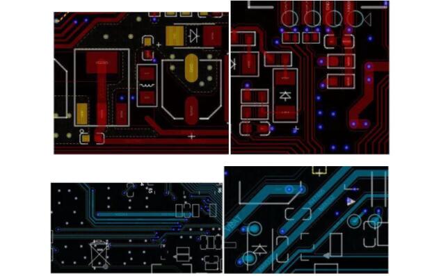
An important part of matching circuit design is PCB layout. Optenni Lab uses a set of electromagnetic simulation multi-port S-parameter models to characterize the PCB layout to support integration with any layout (Figure 4). The simplified layout characterization can also be constructed with the help of microstrip. In both cases, the key components of the synthesis are general-purpose reactors, or inductors (inductors) or capacitive reactors (capacitors). Therefore, even if the layout is fixed to a specific shape such as a Pi-type or T-type topology, an alternative combination of 2N dimensions of L and C is still required. Optenni Lab synthesizes all these structures and sorts the optimized circuits in the list according to performance.
Generally, other components in the RF chain need to be considered, such as baluns, filters, transmission lines/cables, and switches. Such radio frequency components are suitable for a 50 ohm circuit environment, but as mentioned earlier, the antenna impedance may deviate significantly from 50 ohms, so each component is no longer in a suitable impedance environment. Optenni Lab introduced synthetic modular components to match multiple antenna interfaces on the RF chain to achieve the overall chain optimization function of the design goal, such as maximizing the total radiated power of the remaining part of the passband and the required stopband performance. Figure 5 shows the setup schematic.
Correspondingly, the design focus is on the sensitivity problem caused by the small change of the matching component value. Sometimes the seemingly optimal solution looks good during quick inspections, but the results prove to be flashy, because small changes in component values can reduce system efficiency. Figure 6 shows an example where the efficiency of the "optimal" solution is severely reduced due to a component tolerance of 5%. In contrast, the topology ranked No. 3 in rated performance shows the most stable response value. Optenni Lab automatically reorders according to this tolerance sensitivity, and compared with manual analysis, the cost can be greatly reduced: dozens or hundreds of alternative topologies are available.
Multi-antenna specific analysis and synthesis functions
The traditional multi-antenna design relies on the radiating element to achieve resonance at the required frequency, and the isolation between the antennas is achieved through physical separation, but this is limited by industrial design factors. For compact devices, physical separation may have limitations, and coupling effects may pose huge challenges. In addition, for the PCB best design, it is important to be able to calculate the radiation pattern and radiation efficiency of the matching system.
When the coupling effect is strong, the antenna A will be excited, so the antenna B will have induced current, which will affect the far-field radiation pattern of the antenna A. These induced currents depend on the terminal of antenna B. Different from calculating the induced distributed current on the antenna element, this method cancels the induced current on the antenna feed point, and calculates the total radiation pattern through the superposition of the composite far field. The radiation efficiency is then calculated from the total far field.