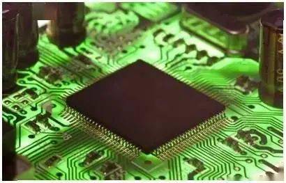
The limitation of base station deployment and site acquisition requires smaller and lighter radio equipment and antennas suitable for 5G massive MIMO(mMIMO). Improved signal processing, high-efficiency devices, and integration from discrete components to front-end modules (FEM) make it possible to meet these needs.
The radio frequency and microwave industries have made considerable progress in realizing commercial sub-6 GHz 5G wireless infrastructure, and millimeter-wave wireless communications have also made progress. Earlier people’s eager attention to 5G has shifted to the formulation of 5G industry standards, and component and system manufacturers have made various adjustments to the applicable and scalable 5G base station architecture. These architectures can be used for mobile users, the Internet of Things, and others. The application provides faster data throughput and higher capacity.
To achieve the evolution from 4G to 5G, and to increase the capacity by 100 times to meet our growing demand for data, fundamental changes are required in the architecture and design of cellular communication radio frequency systems. Facing greater communication demands, such as users, equipment, automobiles, smart meters, low-power wide-area equipment and other machine-to-machine communications, 4G cellular systems using fixed sector antenna systems will face the problem of insufficient capacity. As we all know, in the highest level of communication theory, in order to maximize the wireless channel throughput, it is necessary to maximize the signal-to-noise ratio (SNR) or signal-to-interference and noise ratio (SINR). High-density cellular networks are usually limited by interference rather than noise, and this limitation has forced the evolution of radio frequency architectures into systems that manage interference. This is where the mMIMO system comes in. Compared with 4G systems, mMIMO has more transceivers and antenna units, uses beam-forming signal processing to deliver radio frequency energy to users, and dynamically controls antenna beams by adjusting azimuth and elevation angles to keep them away from interference sources, thereby reducing interference The problems caused. By passing radio frequency energy to users and keeping the signal away from interference, SINR, throughput, and overall system capacity will all be improved.

Challenges of mMIMO
With the realization of 5G antenna arrays and MIMO technology, wireless network operators will face deployment challenges when transitioning from 4G LTE to 5G base stations. This gradual evolution is likely to witness the development of these two technologies in a long time. 4G LTE and 5G base stations have similar physical layouts and are likely to be assembled on existing co-located cellular towers and rooftop facilities. According to the current configuration, interference and coverage gaps are minimized.
As 5G base stations proliferate in existing sites, the available installation space will shrink sharply. In the continuous deployment of 4G LTE base stations in some areas, the installation space has been in short supply. In fact, many cell phone towers have been overloaded, reaching the limit of their carrying capacity, which is reflected in the increasingly chaotic towers in the urban environment.
Figure 1 shows a typical iron tower installation, including two layers of antennas, radios, radio frequency cables, and feeders. The weight of each sector is about 250kg. Wind load, ice load and moment arm are the key factors that affect the superposition of the base station on the tower. During installation, attention should be paid to the recovery ability of the base station and the continuity of service under severe weather conditions.
To meet these challenges, a smaller and denser sub-6 GHz 5G base station design must be used. At the same time, the weight and volume of the base station are still key factors that system designers need to consider, because wireless operators require a lot of labor and equipment costs during installation and subsequent maintenance. In the case of calculating operating costs only based on the size of the antenna's aperture, tower operators have basically switched to a pricing model, that is, using base station weight, aperture area and volume to calculate costs. The initial installation cost also depends on the location, weight and type of installation: tower or roof, single or double, whether to use a crane, etc. The original 4G system is divided into a radio front end and an antenna. The radio front end is usually located on the ground and the passive antenna is installed on the tower. In other devices, the radio and antenna are located on the tower, and the cost of the two is comparable. The 5G mMIMO antenna places active electronic devices on the tower, immediately behind the antenna, so that they are located in an integrated unit.
Of course, the size and dimensions of base stations are always the core issues that RF component suppliers, base station designers, and operators need to consider. The shortage of towers and roof facilities will exacerbate these problems. On the road to achieve commercial-scale millimeter wave 5G connections, it will become very difficult to acquire sites due to the frequency and common sense of physics requiring a distance of 100 meters between base stations. When installed on lamp posts, street signs, bus station shelters, or other structures, the millimeter wave base station equipment needs to be much lighter than when installed alone, so that it does not appear too obtrusive.
In addition, the emphasis on effective omnidirectional radiated power (EIRP) from all walks of life will exacerbate the challenge of site acquisition. Although 4G LTE and sub-6 GHz 5G base stations may show similar EIRP levels when calculating beamforming gain, higher and higher frequencies will require higher RF power to compensate for building penetration losses, and Improve EIRP to achieve a similar degree of indoor coverage. Diffraction loss, aperture efficiency and path loss are all affected by frequency (ie 6 to 12dB per octave). At the same time, due to the skin depth and conductivity of coated glass, conductive (wet) masonry, brick surfaces and other materials, penetration loss will increase sharply at higher frequencies.
Health and safety requirements stipulate the radiation limit of EIRP (1mW per square centimeter) and the exclusion zone should be maintained at an acceptable level during the transition from 4G LTE to 5G. Therefore, increasing the EIRP level will naturally bring about some installation challenges. If the theoretical maximum power is used, these will be combined with the realization of mMIMO beamforming technology. Different from the horizontal orientation of traditional antennas, the beam scanning antenna array can radiate in multiple directions, and even radiate down to the sidewalk. This health and safety-related issue will bring more restrictions on the acquisition of 5G base stations and increase the pressure on the design of smaller and lower power base stations-these base stations must be able to be deployed flexibly while ensuring safety.
Reduce size and weight
When optimizing the size and weight of sub-6 GHz base stations, design factors must be considered. From components to systems, power consumption, efficiency, and heat dissipation are the most important.
The aperture size of the antenna completely depends on the number of antenna elements, and the number of antenna elements depends on the required network capacity and expected interference. Whether the array has 64, 128 or 192 elements, its physical size is determined by the physical characteristics of the array, scanning angle requirements, grating lobe performance and beam width. The size and height of the base station-determined by the underlying electronics and heat dissipation-can be optimized. In this regard, we see a lot of room for improvement.
Compared with a typical LTE system, the key factor that affects the system size that is often overlooked in 5G mMIMO is the sharp increase in signal processing hardware. The mMIMO system can connect 192 antenna elements to 64 transmit/receive (TRx) FEMs. These TRx FEMs have 16 transceiver RFICs and 4 digital front-ends (DFE), which are the same as the 4 transceivers in a typical LTE 4T MIMO In comparison, the performance of digital signal processing can be improved by 16 times (Figure 2). For example, when the frequency is increased from 20 to 100MHz, the bandwidth will increase by 5 times, and the multiple of signal processing is amazing.
The stack demonstrates the functions of a typical mMIMO integrated antenna and radio. The top layer contains antenna units, and the next layer contains radio frequency and digital circuits. Although the TRx FEM, RFIC and DFE layers are separate circuit boards, in fact these three functions will be combined into one or two densely packed functional layers to minimize interconnection.
Perhaps more shocking than the additional hardware in the mMIMO system is the subsequent impact on power consumption and heat dissipation. In the past, power amplifier (PA) power consumption was the most important consideration when designing base station heat sinks and power supplies. Now, the power consumption of signal processing electronics is approaching the power consumption of the onboard power amplifier, and in some cases, it has even exceeded the power consumption of the onboard power amplifier.
By optimizing the signal and waveform adjustment algorithms applied to the transmitted signal, the significant increase in signal processing hardware can be offset to a certain extent. Traditional signal conditioning algorithms, such as peak clipping factor reduction and digital predistortion (DPD), are mainly developed for macro base stations with very high power power amplifiers. Compared with filling mMIMO antennas with power amplifiers of smaller size and lower power, traditional algorithms require more complex and heavier processing workloads. Whether for custom ASIC/SOC or FPGA, these algorithms can easily consume 75% of the available signal processing resources in the DFE processor. By simplifying these algorithms of the 5G mMIMO architecture and reallocating functions into multiple logic blocks, the optimized algorithms in each minimized block will improve signal processing efficiency and reduce overall power consumption.
Figure 4 is a functional block diagram that explains the relationship between digital signal processing and transceiver 16 in the mMIMO system. This architecture is a typical mMIMO design, but there are some differences in logical partitioning (such as 8 or 16-channel DFE), or use discrete components instead of integrated FEM. According to Figure 4, from left to right, the 64 radio and transceiver paths are divided into 16 transceiver RFICs. These 16 transceiver RFICs are used to drive 4 DFEs, and these DFEs will process digital data from 64 channels and connect to the beamforming processor and the baseband interface processor. The advent of RF SOC with direct sampling analog-to-digital converter (ADC) and digital-to-analog converter (DAC) with a conversion rate of approximately 60 GSPS helps to reduce the steps required for analog-to-digital and digital-to-analog conversion in traditional transceiver architectures. Thereby reducing the size and weight of the 5G antenna. By abandoning the use of mixers, converters and local oscillators, the overall component count and cost are reduced.
By adopting advanced MMIC and MCM packaging technology in FEM design, additional cooling functions and space saving advantages can be achieved. Figure 7 shows a simplified mMIMO design, excluding the power supply and fiber interface. The encapsulating shell extends the heat sink to the inside of the shell to save casting weight and improve thermal efficiency. TRx board integrates FEM and RFIC, FEM conducts heat through thermal vias, and RFIC heat will be conducted out through the cover. This allows heat to be dissipated in multiple directions instead of unidirectionally from FEM and RFIC. Heat can be dissipated from the top cover and the bottom of the package through the ground vias and the bottom plate, which is more efficient and effectively reduces the heat sink package. In addition, FEM can channel heat through thermal vias and lids to maximize heat dissipation performance.