

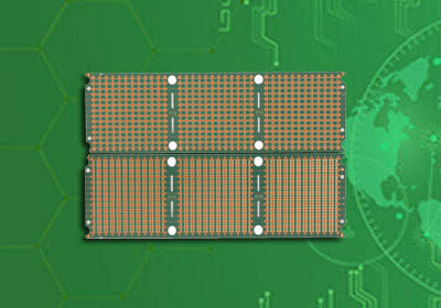

Model : 2 Layers Magnetic Coil PCB
Material : FR4
Layer : 2Layers
Color : Green/White
Finished Thickness : 0.8mm
Copper Thickness : 1OZ
Surface Treatment : Lead-free HASL
Min Trace : 4mil(0.1mm)
Min Space : 4mil(0.1mm)
characteristic : magnetic coil pcb
Application : magnetic coil pcb
Magnetic coil PCB is mainly used for winding, which is mainly used in inductance components. It has a series of advantages such as high precision, good linearity and simple structure. However, the existing technology is difficult to make and has a high scrap rate.

Magnetic Coil PCB testing
Testing Magnetic Coil PCB is an important part of Magnetic Coil PCB testing. So, how many test methods are there for Magnetic Coil PCB? ipcb introduces you:
1. Ordinary Magnetic Coil PCB test
For the coil test, you can use a digital bridge to test the inductance online, because the operating frequency of the inductance coil is often not low, you can set the frequency to test the inductance at a frequency above 10kHz.
2. Transformer Magnetic Coil PCB test
By testing the inductance D value of the transformer's main coil, it can be judged whether the transformer is short-circuited between turns. The specific method is: the digital bridge is set to 0.3V or below, 10kHz or above, and the D value of the main coil inductance is measured. If the D value is greater than 0.1, it is judged that the transformer is damaged and cannot be used.
3. Detection of Hall device Magnetic Coil PCB
Hall sensors have single power supply and dual power supply, current output type and voltage output type. For a single power supply sensor, if no current is detected, the output signal is generally 1/2 of that of a single power supply. If the current is 0, the signal output deviates a lot from the middle value. The sensor can also be quantitatively tested to determine whether the Hall sensor is damaged. The Hall sensor with dual power supplies outputs 0 voltage when it senses 0 current; when it senses other than 0 current, the positive and negative voltage and magnitude of the output change with the magnitude and direction of the induced current.
4. Testing of Relay Magnetic Coil PCB
The common faults of relays include coil disconnection, contact failure, high contact resistance, and contact burnout. The best way to test whether the relay is normal is to power-on test, apply the rated voltage to the Magnetic Coil PCB, and then test the continuity of the contacts.
Model : 2 Layers Magnetic Coil PCB
Material : FR4
Layer : 2Layers
Color : Green/White
Finished Thickness : 0.8mm
Copper Thickness : 1OZ
Surface Treatment : Lead-free HASL
Min Trace : 4mil(0.1mm)
Min Space : 4mil(0.1mm)
characteristic : magnetic coil pcb
Application : magnetic coil pcb
For PCB technical problems, iPCB knowledgeable support team is here to help you with every step. You can also request PCB quotation here. Please contact E-mail sales@ipcb.com
We will respond very quickly.


