Digital equipment is developing in the direction of high speed, low power consumption, small size and high anti-interference. This development trend puts forward many new requirements for the design of printed circuit boards. Protel software has been widely used in China. However, many designers only pay attention to the distribution rate of Protel software, and to improve Protel software to adapt to the changes of equipment characteristics, not only makes the waste of software resources more serious, but also makes the excellent performance of many new devices difficult to play. This paper introduces the general requirements of high frequency circuit wiring. Taking Protel for windows v1.5 software as an example, this paper introduces some special countermeasures that Protel software can provide in high frequency circuit wiring.
Application of Protel software in PCB high frequency circuit wiring

The main results are as follows:
(1) high frequency circuits often have high integration and high line density. Protel for windows v1.5 can provide 16 copper layers and 4 power layers. Reasonable selection of layers can greatly reduce the size of the printed circuit board, make full use of the intermediate layer to set shielding, better realize the nearby grounding, effectively reduce the parasitic inductance, effectively shorten the transmission length of the signal, and greatly reduce the cross interference between signals. These are conducive to the reliable operation of high frequency circuit. The results show that the noise of the four-layer plate is 20 dB lower than that of the double-layer plate with the same material, but the more layers, the more complex the manufacturing process and the higher the cost.
(2) The smaller the lead bend between the pins of high speed circuit, the better. The lead wire of high frequency circuit wiring is best to use full straight line, and 45 ° broken line or arc turning is needed. This requirement is only used to improve the fixed strength of steel foil in low-frequency circuit, but to meet this requirement in high-frequency circuit can reduce the external transmission and coupling of high-frequency signal. When using Protel for routing, you can preset it in the following two places: one is to reserve 45 / 90 lines or 90 arcline lines in the "track mode" submenu of the "options" menu, and the other is to select Add arcs in the "routing pass" dialog box opened by the setup autoroute item in the "automatic" menu to form an arc at the corner of the automatic routing.
(3) The shorter the lead between the pins of PCB high frequency circuit, the better. In order to satisfy the shortest route, PROTEL's most effective method is to reserve the route for single key high-speed network before the automatic market line. First, the changenet dialog box will appear in the submenu of netlst menu in editnet, and the optimize method routing optimization mode in this dialog box can be selected as the shortest. Secondly, when considering the overall layout of the parts, the placement tools shove is used to compare and adjust the components in auto and density in Auto to make them compact. In combination with the length function in netlist menu and the length of selection function of length of selection function of info menu, the wiring length of the selected key network can be measured.
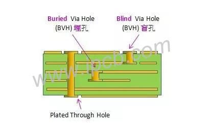
(4) The less the lead layer alternation between the pins of high frequency circuit device, the better. The so-called lead layer alternation means that the less through holes are used in the component connection process, the less the 0.5pf distributed capacitance brought by the measuring holes. By reducing the number of holes, the speed can be significantly improved. Protel software provides this function in particular. It has a high-level column in the routingpass dialog box opened by the setup autoroute project of the automatic menu, which can turn on smoothing.
(5) Attention should be paid to the cross interference caused by short-range signal lines in high-frequency circuit wiring. If the parallel distribution cannot be avoided, the interference can be greatly reduced in the large area opposite to the parallel signal lines. The parallel lines in the same layer are almost inevitable, but the direction of the straight line walking in the two adjacent layers must be vertical, which is not difficult to do in Protel, but it is easy to be ignored. In the routing lager dialog box opened by the setup autoroute item of the auto menu, it is allowed to determine the orientation of each layer in advance. There are three types of "vertical" and "nopreference". Users are used to choosing nopreference when there is no specific direction, so they think that the distribution rate is very high. However, in high-frequency circuit wiring, it is better to alternately use horizontal and vertical wiring in adjacent layers, which can not avoid parallel wiring of the same layer, but the ground wire can be placed on the opposite side of the printed circuit board to reduce interference. This is a common double-sided board. The multi-layer board can use the medium power layer to realize this function. Protel software only provides a simple filling function to meet this requirement. Now Protel also provides a more powerful function under windows, which places polygons in the place option of the edit menu, that is, polygon mesh with copper foil. If the polygon is placed as the side of the whole printed circuit board, and the gate is connected to the GND network of the circuit, the function can realize the copper discharging operation on one side of the whole circuit board. Copper laying circuit board can not only improve the above high frequency anti-interference ability, but also has great advantages on heat dissipation and PCB strength. In addition, if tin plated grid is added to the fixed part of the metal chassis of the circuit board, it can not only improve the fixation strength and ensure good contact, but also form a suitable public circuit by using the metal chassis. When you turn this feature on in the software menu, you see the placepolygonplane dialog box, which asks if you want to connect the polygon mesh bars to the network. If you connect to the exit dialog box, you are prompted for the name of the network you want to connect to. Given the connection to the GND network, you will be able to act as a shield, and you will also be asked if you are laying copper with horizontal bars, horizontal bars, vertical bars, or grids. network