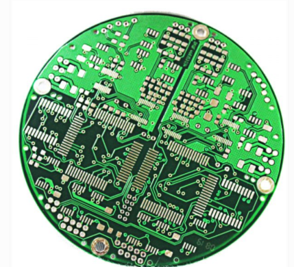
1. Common impedance interference of ground wire in PCB design
Said ground zero potential in the circuit on the circuit diagram, and used as a circuit in other public reference points, each point in the actual circuit due to the existence of the ground wire (copper film line) impedance, brings the total impedance interference, therefore when wiring, has the ground symbol point can not be casually together, this is likely to cause harmful coupling and affect the normal work of the circuit.

2. How to connect ground wire in PCB design
Usually in an electronic system, ground cables are classified into system ground, shell ground (shielded), digital ground (logical) and analog ground, etc. When connecting ground cables, you should pay attention to the following points:
1) Correctly select single point grounding and multi-point grounding
In low-frequency circuits, the signal frequency is less than 1MHz, the inductance between the wiring and components can be ignored, and the voltage drop generated on the resistance of the ground circuit has a greater impact on the circuit, so the single point grounding method should be used. When the signal frequency is greater than 10MHz, the inductance of the ground cable is greatly affected. Therefore, the nearby multi-point grounding method is recommended. When the signal frequency ranges from 1 MHZ to 10MHz, the length of the ground cable should not exceed 1/20 of the wavelength if the single point grounding method is adopted. Otherwise, the multi-point grounding method should be adopted.
2) Separate digital and analog
The circuit board has both digital circuit, and analog circuit, should make them separate as far as possible, and ground wire can not be mixed, should be connected with the ground wire end of the power supply (it is best to connect the power supply end respectively). Try to maximize the area of the linear circuit. General digital circuit has strong anti-interference ability. The noise tolerance of TTL circuit is 0.4~0.6V, and that of CMOS digital circuit is 0.3~0.45 times of power supply voltage. However, as long as there is microvolt level noise in analog circuit, it is enough to make it work abnormally. So the two types of circuits should be laid out and routed separately.
3) Make the ground as thick as possible
If the ground wire is very thin, the ground potential will change with the change of the current, resulting in interference of the signal of the electronic system, especially the analog circuit. Therefore, the ground wire should be as wide as possible, generally greater than 3mm is appropriate.
4) Form a closed loop with the grounding wire
When there is only digital circuit on the circuit board, the ground wire should form a loop, which can significantly improve the anti-interference ability, this is because when there are many integrated circuits on the circuit board, if the ground wire is very thin, it will cause a larger grounding potential difference, and the ring ground wire can reduce the grounding resistance, thus reducing the grounding potential difference.
5) The grounding point of the same circuit should be as close as possible, and the power filter capacitor of the circuit should also be connected to the grounding point of the circuit.
6) The connection of the general ground wire
The main ground wire must be connected from weak current to strong current in strict order of high frequency, medium frequency and low frequency. The high frequency part had better use the large area surrounding type ground wire, in order to ensure a good shielding effect.