What is differential wiring: Differential wiring is mainly to distinguish the signal transmission method of a traditional signal line corresponding to a ground wire. Differential signal transmission mainly involves signal transmission on two wires, and the two signals are equal in amplitude and opposite in phase. Compared to traditional single-ended
What is differential wiring: Differential wiring is mainly to distinguish the signal transmission method of a traditional signal line corresponding to a ground wire. Differential signal transmission mainly involves signal transmission on two wires, and the two signals are equal in amplitude and opposite in phase.

Compared with the traditional single-ended signal, it has the advantages of strong anti-interference, can effectively suppress electromagnetic interference and time sequence positioning preparation.
How to lay out the differential line?
Two points should be paid attention to in the layout of the differential pair when designing the circuit board:
One is that the length of the two lines should be as long as possible;
The other is that the distance between the two wires (this distance is determined by the differential impedance) must be kept constant, that is, it must be kept parallel.
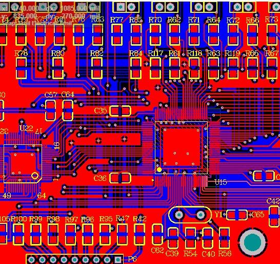
There are usually two parallel methods. One is that two lines on the PCB are run on the same side-by-side, and the other is that two lines run on two adjacent layers (over-under). Generally, there are more ways to implement it by agreeing to the wiring layer. To use differential wiring, it makes sense that both the signal source and the receiving end are differential signals. Therefore, it is impossible to use differential wiring for a clock signal with only one output terminal. The matching resistance between the differential line pairs at the receiving end is usually added, and its value should be equal to the value of the differential impedance, so the signal quality will be better. The wiring method of the differential pair should be close and parallel appropriately. The reason for proper proximity is that the distance will affect the value of differential impedance, which is an important parameter for designing a differential pair. The need for parallelism is also to maintain the consistency of the differential impedance.
If the two lines are suddenly far and near, the differential impedance will be inconsistent, which will affect the signal integrity and timing delay.