What is electromigration and why does it occur? And more importantly, how to prevent it? A simple round of PCB board and IC electromigration analysis. The purpose is to prevent these devices from short-circuiting and open-circuiting under different conditions. Several industry standards have been developed for this purpose. What do you need to know about these standards and how electromigration can cause new equipment to fail
Electromigration in electrons
As more components pile up in a smaller space, the electric field between two conductors with a specified potential difference becomes larger. This leads to a number of safety issues in high-voltage electronics, particularly electrostatic discharge (ESD). A high electric field between two conductors separated by air causes the air to undergo dielectric breakdown, which creates arcs and current pulses in the surrounding circuit. To prevent these discharges in a PCB or other device, separate the conductors at a distance that depends on the potential difference between the conductors.

The clearance distance above is important for safety and protection against equipment failure, but the distance across the substrate is also important. Another point to consider is the distance between conductors across the dielectric. In PCB, this is called creepage distance, and its requirements (and electrical clearance) are defined in the IPC2221 standard. When the spacing between conductors is small, the electric field can be large, leading to electrical migration.
When the current density in the conductor is large (in an IC), or when the electric field between two conductors is large (in a PCB), the mechanism that drives the electromigration can be described as exponential growth. To prevent electromigration, you can use three levers to pull in your design:
Increase the spacing between conductors (in a PCB)
Reduce the voltage between conductors (in PCB)
To run equipment at a lower current (in IC)
Electromigration in ics: open and short circuits
In IC interconnection, the main force is not the electric field between the two conductors and the subsequent ionization. In contrast, solid-state electromigration is due to electron momentum transfer (scattering) at high current densities (typically "10,000 A/cm2") causing the metal to move along A conductive path (in this case, the metal interconnect itself). Electromigration follows the Ahrrenius process, so the migration speed increases with the increase of interconnect temperature.
The forces involved in electromigration of copper are shown below. Wind force is the force exerted on metal ions due to the scattering of electrons from metal atoms in the lattice. This repeated ionization and momentum transfer to the free metal ions causes them to diffuse toward the anode. This migration process has activation energy. Directional diffusion begins when the energy transferred to the metal atoms exceeds the Ahrrenius activation process, which is guided by the concentration gradient (Fick's Law).
When the metal is pulled to the surface of a conductor, it begins to build structures that can bridge the two conductors, causing a short circuit. It can also deplete the metal on the anode side of the interconnect, leading to an open circuit. The SEM image below shows the results of extended electromigration between two conductors. As the metal migrates along the surface, it leaves gaps (open circuits) or creates whiskers that connect to adjacent conductors (short circuits). In extreme cases with through-holes, electromigration can even deplete the conductor beneath the overlay.
Electromigration in PCBS: Dendritic growth
A similar effect occurs in PCBS, resulting in two possible forms of electromigration:
As described above, electromigration along the surface
The formation of semiconductor salts leads to electrochemical growth of dendritic dendritic structures
These effects are controlled by different physical processes. The current density between the two conductors can be very low because of the very large size of the metal wire compared to the cross section of the IC interconnect. In these cases, migration occurs at high current densities, resulting in the same type of short-cut growing over time. At the surface layer, subsequent oxidation may occur as the conductor is exposed to air.
In the second case, electromigration is an electrolytic process. The field drives electrochemical reactions in the presence of water and salts. Electrolytic electromigration requires water on the surface and high direct current between the two conductors, which drives electrochemical reactions and dendritic growth. The migrating metal ions dissolve in an aqueous solution and diffuse throughout the insulating substrate. IPC2221 comes into play here because increasing the distance between adjacent conductors reduces the electric field between them, thus inhibiting the reaction that drives electrolytic electric migration.
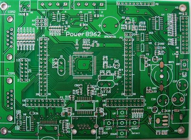
Electromigration analysis in the new layout requires checking the design to ensure trace gaps do not violate design rules or industry standards. If you have access to some basic PCB or IC layout tools, you can check the layout against these rules and find any violations. As ICS and PCBS continue to shrink, electromigration analysis will only become more important to ensure reliability.