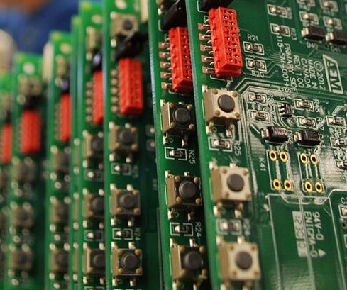
Disassembly and welding skills of patch components

Welding technology for component maintenance
Solution:
Master the skills of temperature control, preheating and light touch during disassembly and welding
The welding temperature shall be controlled at about 200 ~ 250 degree Celsius
The components to be welded shall be preheated at about 100 degree Celsius for 1 ~ 2 minutes
In the process of learning maintenance, you should master the disassembly and welding skills of patch components. For the disassembly and welding of chip mounted components, 200 ~ 280 degree Celsius temperature regulating pointed soldering iron should be selected.
The substrates of chip mounted resistors and capacitors are mostly made of ceramic materials, which are easy to crack due to collision. Therefore, the skills of temperature control, preheating, light touch and so on should be mastered during disassembly and welding. Temperature control means that the welding temperature shall be controlled at about 200 ~ 250 degree Celsius. Preheating refers to preheating the elements to be welded in an environment of about 100 degree Celsius for 1 ~ 2 minutes to prevent sudden thermal expansion and damage of the elements. Light touch means that when * * is working, the soldering iron head should first heat the solder joint or guide belt of the printed board, and try not to touch the components. In addition, the welding time should be controlled at about 3 seconds. After welding, let the circuit board cool naturally at room temperature. The above methods and techniques are also applicable to the welding of SMD crystal diodes and triodes.
The number of pins of SMD IC is large, the spacing is narrow and the hardness is small. If the welding temperature is improper, it is very easy to cause faults such as short circuit of pin solder, false soldering or separation of printed circuit copper foil from printed board. When removing the chip integrated circuit, adjust the temperature of the temperature regulating soldering iron to about 260 degree Celsius, suck all the soldering tin of the integrated circuit pins with the soldering iron head and the tin absorber, gently insert the pointed nose tweezers into the bottom of the integrated circuit, heat with the soldering iron, and gently lift the integrated circuit pins one by one with tweezers to gradually separate the integrated circuit pins from the printed board. When lifting the integrated circuit with tweezers, it must be carried out synchronously with the heated part of the soldering iron to prevent the circuit board from being damaged by too fast.
Before replacing with a new integrated circuit, all the solder left by the original integrated circuit shall be removed to ensure the flatness and cleanness of the pad. Then polish and clean the IC pins to be welded with fine sandpaper and evenly tin them. Then align the IC pins to be welded with the corresponding solder joints of the printed board. During welding, gently press them on the IC surface by hand to prevent the IC from moving. The other hand * * acts as an electric soldering iron dipped with an appropriate amount of solder to weld and fix the pins at the four corners of the circuit with the circuit board, Check again to confirm the model and direction of the integrated circuit, and then conduct formal welding. Adjust the temperature of the soldering iron to about 250 degree Celsius. One hand holds the soldering iron to heat the integrated circuit pins, and the other hand sends the soldering wire to the heating pins for welding until all pins are heated and welded. Finally, carefully check and eliminate the short circuit and false welding of the pins. After the solder joint cools naturally, Clean the circuit board and solder joint again with a brush dipped in anhydrous alcohol to prevent welding slag.
Before troubleshooting the module circuit board, it is advisable to clean the printed board with a brush dipped in anhydrous alcohol, remove the dust, welding slag and other sundries on the board, and observe whether there is false welding or welding slag short circuit on the original printed circuit board, and find the fault point early to save maintenance time.