1. About the test coupon.
The test coupon is used to measure whether the characteristic impedance of the produced PCB board meets the design requirements with TDR (Time Domain Reflectometer). Generally, the impedance to be controlled has two cases: a single line and a differential pair. Therefore, the line width and line spacing on the test coupon (when there is a differential pair) should be the same as the line to be controlled. The important thing is the location of the grounding point during the measurement. In order to reduce the inductance of the ground lead, the grounding place of the TDR probe is usually very close to the probe tip. Therefore, the distance and method between the signal measurement point and the ground point on the test coupon Must match the probe used.

2. In high-speed PCB design, the blank area of the signal layer can be coated with copper, and how should the copper coating of multiple signal layers be distributed on the ground and power supply?
Generally, the copper plating in the blank area is mostly grounded. Just pay attention to the distance between the copper and the signal line when applying copper next to the high-speed signal line, because the applied copper will reduce the characteristic impedance of the trace a little. Also be careful not to affect the characteristic impedance of other layers, for example in the structure of the dual stripline.
3. Is it possible to use the microstrip line model to calculate the characteristic impedance of the signal line on the power plane? Can the signal between the power supply and the ground plane be calculated using the stripline model?
Yes, when calculating the characteristic impedance, both the power plane and the ground plane must be regarded as reference planes. For example, a four-layer board: top layer-power layer-ground layer-bottom layer. At this time, the characteristic impedance model of the top layer is a microstrip line model with the power plane as the reference plane.
4. Can test points be automatically generated by software on high-density printed boards under normal circumstances to meet the test requirements of mass production?
Generally, whether the software automatically generates test points to meet the test requirements depends on whether the specifications for adding test points meet the requirements of the test equipment. In addition, if the wiring is too dense and the specifications for adding test points are strict, it may not be possible to automatically add test points to each segment of the line. Of course, you need to manually fill in the places to be tested.
5. Will adding test points affect the quality of high-speed signals?
Whether it will affect the signal quality depends on the method of adding test points and how fast the signal is. Basically, additional test points (not using the existing via or DIP pin as test points) may be added to the line or pulled out a short line from the line. The former is equivalent to adding a small capacitor on the line, while the latter is an extra branch. Both of these conditions will affect the high-speed signal more or less, and the degree of the effect is related to the frequency speed of the signal and the edge rate of the signal. The magnitude of the impact can be known through simulation. In principle, the smaller the test point, the better (of course, it must meet the requirements of the test tool) the shorter the branch, the better.
6. Several PCBs form a system, how should the ground wires between the boards be connected?
When the signal or power supply between each PCB board is connected to each other, for example, if board A has a power supply or a signal is sent to board B, there must be an equal amount of current flowing from the ground back to board A (this is Kirchoff current law). The current on this ground will find a place with low impedance to flow back. Therefore, at each interface, whether it is power or signal interconnection, the number of pins allocated to the ground layer should not be too small to reduce the impedance, which can reduce the noise on the ground layer. In addition, you can also analyze the entire current loop, especially the part with a large current, and adjust the connection of the ground layer or ground wire to control the current flow (for example, make a low impedance somewhere so that most of the current flows from this Go somewhere) to reduce the impact on other more sensitive signals.
7. Two characteristic impedance formulas that are often referred to:
a. Microstrip
Z={87/[sqrt(Er+1.41)]}ln[5.98H/(0.8W+T)] where W is the line width, T is the copper thickness of the trace, and H is the trace to the reference plane Distance, Er is the dielectric constant of the PCB material. This formula must be applied when 0.1<(W/H)<2.0 and 1<(Er)<15.
b. stripline
Z=[60/sqrt(Er)]ln{4H/[0.67π(T+0.8W)]} where H is the distance between the two reference planes, and the trace is located in the middle of the two reference planes. This formula must be applied when W/H<0.35 and T/H<0.25.
8. Can a ground wire be added to the middle of the differential signal line?
It is generally not possible to add a ground wire in the middle of the differential signal. Because the important point of the application principle of differential signals is to take advantage of the benefits of coupling between differential signals, such as flux cancellation, noise immunity and so on. If you add a ground wire in the middle, it will destroy the coupling effect.
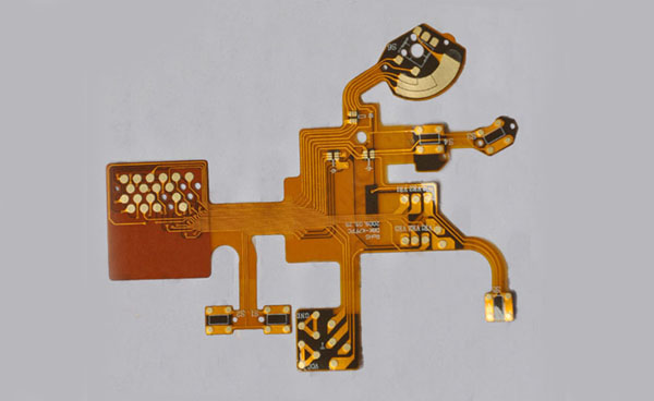
9. Does rigid-flex board design require special design software and specifications?
You can use general PCB design software to design a flexible printed circuit(Flexible Printed Circuit). It is also produced by FPC manufacturers in Gerber format. Because the manufacturing process is different from that of general PCBs, various manufacturers will have their limitations on small line widths, small line spacings, and small vias based on their manufacturing capabilities. In addition, it can be reinforced by laying some copper skin at the turning point of the flexible circuit board. The inspection standard of soft board is usually based on IPC6013
10. What is the principle of properly selecting the grounding point between the PCB and the case?
The principle of selecting the PCB and shell grounding points is to use the chassis ground to provide a low-impedance path for the returning current and to control the path of the returning current. For example, usually near high-frequency devices or clock generators, fixed screws can be used to connect the ground layer of the PCB to the chassis ground to minimize the area of the entire current loop and reduce electromagnetic radiation.