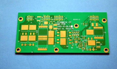
Multi-layer boards are multi-layer or multi-layer printed circuit boards, which are circuit boards composed of two or more conductive layers (copper layers) superimposed on each other. The copper layer is bonded together by the resin layer (prepreg). Drilling and electroplating have been completed, and the multi-substrate is manufactured by stacking two or more circuits on top of each other and has a reliable pre-set interconnection between them. Because before all the layers are rolled together. This technique violated the conservative production process from the beginning. The two innermost layers are composed of traditional double-sided panels, while the outer layer is different. The inner substrate will be drilled, through-hole electroplated, pattern transferred, developed, and etched before being laminated by independent single-sided panels. The outer layer to be drilled is the signal layer, which is plated through in such a way as to form a balanced copper ring on the inner edge of the through hole, and then the layers are rolled together to form a multi-substrate, which can use wave crests Welding connects components to each other.

Makes its price relatively high. A multilayer or multilayer printed circuit board is a circuit board composed of two or more conductive layers (copper layers) superimposed on each other. The copper layer is bonded together by the resin layer (prepreg). Multi-substrate is the most complicated type of printed circuit board. Due to the complexity of the manufacturing process, the low throughput and the difficulty of redoing.
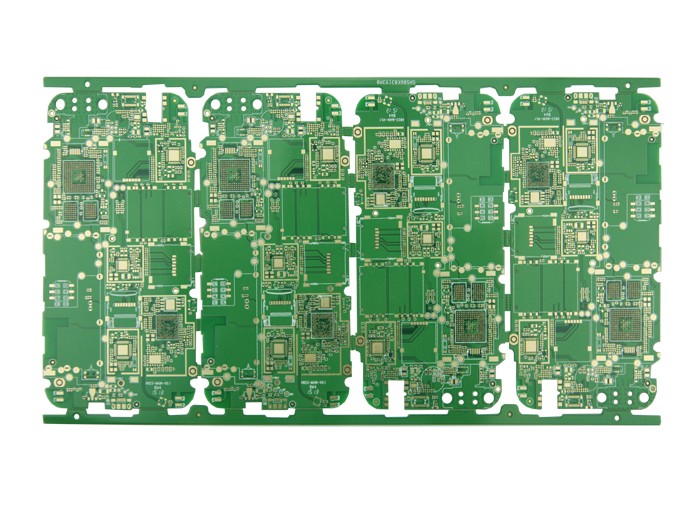
This results in a high concentration of interconnect lines due to the increase in integrated circuit packaging density. This necessitates the use of multiple substrates. Unforeseen design problems such as noise, stray capacitance, crosstalk, etc. appear in the layout of the printed circuit. Therefore, the printed circuit board design must focus on minimizing the length of signal lines and avoiding parallel routes. Obviously, in single-panel, or even double-panel, these requirements cannot be satisfactorily answered due to the limited number of crossovers that can be achieved. In the case of a large number of interconnection and crossover requirements, the circuit board must be expanded to more than two layers to achieve a satisfactory performance, thus presenting a multi-layer circuit board. Therefore, the original intention of manufacturing multi-layer circuit boards is to provide more freedom in selecting appropriate wiring paths for complex and/or noise-sensitive electronic circuits.
Two of the layers are on the outer surface, and the multilayer circuit board has at least three conductive layers. The remaining layer is integrated in the insulating board. The electrical connection is usually achieved through plated through holes on the cross-section of the circuit board. Unless otherwise specified, multilayer printed circuit boards, like double-sided boards, are generally plated through holes.
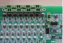
At present, the mainstream circuit board assembly technology in the SMT industry should not be "full board reflow soldering (Reflow)". Of course, there are other circuit board soldering methods. This full board reflow soldering can be divided into single-sided reflow soldering and Double-sided reflow and single-sided reflow are rarely used by people now, because double-sided reflow can save the space of the circuit board, which means that the production can be made smaller, so most of the boards seen on the market It belongs to the double-sided reflow process.
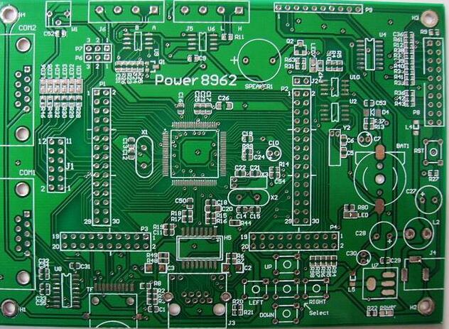
Double-sided circuit board characteristics.
The difference between single-sided circuit boards and double-sided circuit boards is the number of copper layers. Double-sided circuit boards have copper on both sides of the circuit board, which can be connected through vias. However, there is only one layer of copper on one side, which can only be used for simple circuits, and the holes made can only be used for plug-in connections. The technical requirement of double-sided circuit boards is that the wiring density becomes larger, the hole diameter is smaller, and the hole diameter of the metallized hole becomes smaller and smaller. The quality of the metallized holes on which the layer-to-layer interconnection depends is directly related to the reliability of the printed board. As the pore size shrinks, the debris that did not affect the larger pore size, such as brush debris and volcanic ash, once left in the small hole, will cause electroless copper and electroplating to lose its effect, and there will be holes without copper and become holes. Deadly metallized killer.
There are wiring on both sides of Double-Sided Boards. However, to use wires on both sides, there must be a proper circuit connection between the two sides. The "bridge" between such circuits is called a via. A via is a small hole filled or coated with metal on the PCB, which can be connected with the wires on both sides. Because the area of the double panel is twice as large as that of the single panel, and because the wiring can be interleaved (it can be wound to the other side), it is more suitable for use in circuits that are more complicated than the single panel.