Electromagnetic compatibility refers to the ability of a device or system to work normally in its electromagnetic environment and not cause unbearable electromagnetic interference to anything in the environment. The purpose of electromagnetic compatibility design is to enable electronic equipment to suppress all kinds of external interference, so that the electronic equipment can work normally in a specific electromagnetic environment, and to reduce the electromagnetic interference of the electronic equipment itself to other electronic equipment.
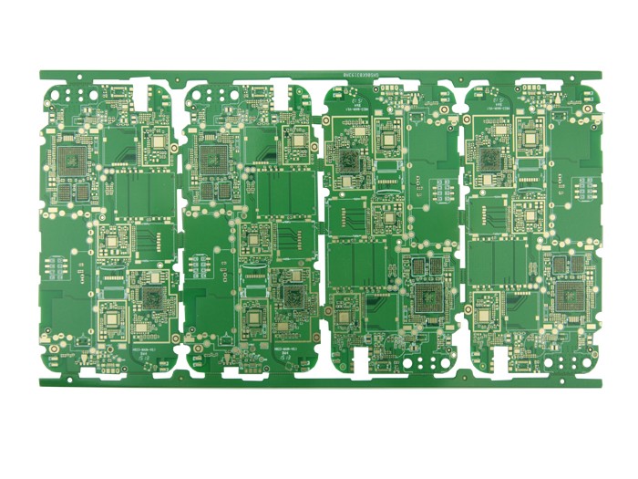
As the sensitivity of electronic equipment becomes higher and higher, the ability to receive weak signals becomes stronger, and the frequency band of electronic products becomes wider and smaller, and the electronic equipment is required to have stronger anti-interference ability. The electromagnetic waves generated by some electronic devices can easily cause electromagnetic interference to other electronic devices around them, causing malfunctions or affecting signal transmission. In addition, excessive electromagnetic interference will cause electromagnetic pollution, endanger people's health, and destroy the ecological environment. The article analyzes several key technologies of electromagnetic compatibility in PCB design(printed circuit board, also called printed circuit board).

1. Power supply design
The power supply of electronic equipment is widely connected with other functional units. On the one hand, unnecessary signals generated in the power supply can be easily coupled to each functional unit. On the other hand, unnecessary signals in a unit may be coupled to the common impedance of the power supply. Go to other units. Therefore, the following measures should be taken in the power supply design.
(1) According to the current size of the printed circuit board, try to increase the width of the power line as much as possible, reduce the loop resistance, and make the direction of the power line and the ground line consistent with the direction of data transmission; at the same time, use the power layer and the ground layer in the multilayer PCB, To reduce the line length from the power line to the power layer or ground layer. This helps to enhance the anti-noise ability;
(2) Where possible, make the power supply separately supply power to each functional unit, and all circuits using the common power supply are as close as possible to each other and are compatible with each other;
(3) Use a power filter on the AC and DC mains to prevent external interference from entering the equipment through the power supply, prevent switching transients and other signals generated inside the equipment from entering the primary power supply, and effectively isolate the input and output lines of the power supply and the input of the filter And output line;
(4) Perform effective electromagnetic field shielding on the power supply, and isolate the high-voltage power supply from sensitive circuits as much as possible, especially the switching power supply, which will cause high-frequency radiation and conduction disturbance. Use an electrostatic shielded power transformer to suppress the common mode on the power line Interference, multiple shielding isolation transformers have better performance;
(5) The power supply should maintain low output impedance for all circuit functional states. Even in the radio frequency range, the output capacitor should exhibit low impedance, while ensuring that the regulator has a fast enough response time to suppress high-frequency ripple and transients. Loading effect
(6) The rectifier diode should work at the lowest current density to provide sufficient RF bypass for the Zener diode;
(7) The power transformer should be symmetrically balanced, not a power-balanced transformer, and the core material used should be the lower limit of its saturation magnetic induction (Bm). In any case, it must be ensured that the iron core is not driven to a saturated state. The core structure of the transformer should be D type and C type, and E type is the second.
2. Ground wire design
Ground noise, that is, the potential difference between the ground wires of each part of the system or the ground noise caused by the existence of ground impedance. Since the grounding system has the problem of ground potential difference, the corresponding grounding method must be selected according to the characteristics of the PCB in the process of designing the grounding of the product. In the design of electronic products, grounding is an important method to control interference. If grounding and shielding can be properly combined, most interference problems can be solved. The ground wire structure in electronic products roughly includes system ground, chassis ground, digital ground and analog ground. The following points should be paid attention to in the ground wire design:
(1) The grounding wire should be as thick as possible. If the ground line is very thin, the ground potential will fluctuate with the change of the current, causing the timing signal level of the electronic product to be unstable, and the anti-noise performance is reduced. Therefore, the ground wire should be as thick as possible in the design, so that it can pass three times the allowable current of the printed circuit board. If possible, the width of the ground wire should be greater than 3mm.
(2) Correctly choose the grounding method. The purpose of the single-point grounding setting is to prevent the current and the radio frequency current from the subsystems of two different reference levels from passing through the same return path and causing common impedance coupling. This grounding method is more suitable for low-frequency PCBs, which can reduce the influence of distributed transmission impedance. However, in a high-frequency PCB, the inductance of the return path becomes the main part of the line impedance at high frequencies. Therefore, in order to minimize the ground impedance in a high-frequency PCB, a multi-point grounding method is usually used. The most important thing for multi-point grounding is to require the minimum length of the grounding lead, because a longer lead means greater inductance, thereby increasing the ground impedance and causing a ground potential difference. The mixed grounding structure is a combination of single-point grounding and multi-point grounding. This kind of structure is commonly used when there are high and low mixed frequencies in the PCB, that is, single-point grounding is present at low frequencies, and multi-point grounding is present at high frequencies.
(3) The digital ground is separated from the analog ground. There are both high-speed logic circuits and linear circuits on the circuit board. They should be separated as much as possible. The ground wires of the two should not be mixed, and they should be connected to the ground wires of the power supply terminal. The ground wire of the low-frequency circuit should be grounded in parallel at a single point as much as possible. When the actual wiring is difficult, it can be partially connected in series and then grounded in parallel. The high-frequency circuit should be grounded at multiple points in series, the ground wire should be short and thick, and the grid-shaped large-area ground foil should be used around the high-frequency component as much as possible. Try to increase the grounding area of the linear circuit as much as possible.
(4) The ground wire forms a closed loop. When designing the grounding system of a printed circuit board composed of only digital circuits, making the grounding wire a closed circuit can significantly improve the anti-noise capability. Because there are many integrated circuit components on the printed circuit board, especially when there are components that consume more power, due to the limitation of the thickness of the ground wire, a large potential difference will be generated on the ground wire, which will cause the noise immunity to decrease. The grounding wire forms a loop, which will reduce the potential difference and improve the anti-noise ability of electronic equipment.
(5) Use an optical isolator to cut off the ground loop interference. Optical connection usually uses optical coupler and optical fiber connection. The parasitic capacitance of the optocoupler is generally 2pF, which can provide good isolation for high frequencies. Optical fiber connection has almost no parasitic capacitance, but it is expensive and inconvenient to install and maintain.
3. Bypass and decoupling design
Bypass is to transfer unwanted common-mode RF energy from components or cables. The main function of bypass capacitors is to generate an AC component to eliminate unwanted energy that enters the susceptible area. Decoupling refers to removing The main function of the decoupling capacitor is to provide a local DC power supply to the components to reduce the propagation of switching noise on the board and to guide the noise to the ground.
3.1 Selection of capacitor
By selecting the bypass and decoupling capacitors, the self-resonant frequency of the required capacitor can be calculated through the logic series and the clock speed used, and the capacitor value can be selected according to the frequency and the capacitive reactance in the circuit. For the package size, try to choose SMT capacitors with lower lead inductance instead of through-hole capacitors. In addition, product designs often use parallel decoupling capacitors to provide a larger operating frequency band and reduce ground imbalance. Parallel capacitor system, when the operating frequency is higher than the self-resonant frequency, the large capacitor exhibits inductive impedance and increases with the increase of frequency; while the small capacitor exhibits capacitive impedance and decreases with the increase of frequency, and at this time, the capacitance of the entire capacitor circuit The impedance is smaller than the impedance of a single capacitor.
3.2 Bypass capacitor configuration
Bypass capacitors are generally used as high-frequency bypass devices to reduce the transient power requirements of the power module. Generally, aluminum electrolytic capacitors and tantalum capacitors are more suitable for bypass capacitors. The capacitance value depends on the transient current requirements on the PCB. In the range of 10~470LF, if there are many integrated circuits, high-speed switching circuits and power supplies with long leads on the PCB, large-capacity capacitors should be selected.
3.3 Decoupling capacitor configuration
(1) The power input terminal is connected with an electrolytic capacitor of 10~100LF. If possible, it is better to connect with more than 100LF;
(2) In principle, each integrated circuit chip should be equipped with a 0.01pF ceramic capacitor. If the printed board gap is not enough, a 1~10pF tantalum capacitor can be arranged for every 4~8 chips;
(3) For devices with weak anti-noise ability and large power changes when shutting down, such as RAM and ROM storage devices, a decoupling capacitor should be directly connected between the power line of the chip and the ground line;
(4) Capacitor leads should not be too long, especially for high-frequency bypass capacitors;
(5) Because there are contactors, relays, buttons and other components in the printed board, large spark discharges will be generated during operation, and RC circuits must be used to absorb the discharge current. Generally, R takes 1~2K, and C takes 2.2~47LF;
(6) The input impedance of CMOS is very high, and it is susceptible to induction, so when in use, the unused terminal should be grounded or connected to a positive power supply.
4. Design of mixed signal circuit board
Knowing the path and method of current return to ground is the key to optimizing mixed-signal circuit board design. You can't just consider where the signal current flows, and ignore the specific path of the current. If the ground layer must be divided, and the wiring must be routed through the gap between the divisions, a single-point connection can be made between the divided grounds to form a connection bridge between the two grounds, and then wiring through the connection bridge. In this way, a direct current return path can be provided under each signal line, so that the loop area formed is small. Pay attention to the following points in the mixed-signal PCB design process:
(1) Divide the PCB into independent analog and digital parts, realize the division of analog and digital power, and place the A/D converter across the partitions;
(2) Do not divide the ground. Lay a uniform ground under the analog part and the digital part of the circuit board;
(3) In all layers of the circuit board, digital signals can only be wired on the digital part of the circuit board, and analog signals can only be wired on the analog part of the circuit board;
(4) The wiring cannot cross the gap between the divided power supply planes, and the signal line that must cross the gap between the divided power supplies should be located on the wiring layer close to the large area ground;
(5) Analyze the path and method of the actual return ground current flow;
(6) Adopt correct layout and wiring rules.
In short, as electronic products become more complex, high-speed, and dense, the design requirements for PCB boards are getting higher and higher, especially the design problems of electromagnetic compatibility are becoming more and more prominent., Bypass, decoupling and mixed-signal circuits and other reasonable design.