0 Preface
PCB is the abbreviation for Printed Circuit Board in English. Generally, conductive patterns made of printed circuits, printed components or a combination of both on insulating materials according to a predetermined design are called printed circuits. The conductive pattern that provides electrical connections between components on an insulating substrate is called a printed circuit. In this way, the printed circuit or the finished board of the printed circuit is called a printed circuit board, also called a printed circuit board or a printed circuit board. PCB board is inseparable from almost all electronic equipment we can see, from electronic watches, calculators, general-purpose computers, to computers, communication electronic equipment, aviation, aerospace, military weapon systems, as long as there are electronic components such as integrated circuits. Devices and their electrical interconnection all use PCB, and its performance is directly related to the quality of electronic equipment. With the rapid development of electronic technology, electronic products are becoming more and more high-speed, high-sensitivity, and high-density. This trend has led to serious electromagnetic compatibility (EMC) and electromagnetic interference problems in PCB circuit board design. Electromagnetic compatibility design has become Technical problems to be solved urgently in PCB design.

1 Electromagnetic compatibility
Electromagnetic Compatibility (Electro-Magnetic Compatibility, EMC for short) is an emerging comprehensive discipline, which mainly studies electromagnetic interference and anti-interference issues. Electromagnetic compatibility means that the electronic equipment or system does not reduce the performance index due to electromagnetic interference under the specified electromagnetic environment level, and the electromagnetic radiation generated by them is not greater than the limited limit level, and does not affect the normal operation of other systems. And achieve the goal of non-interference between equipment and equipment, system and system, and work together reliably. Electromagnetic interference (EMI) is caused by electromagnetic interference sources transferring energy to sensitive systems through coupling paths. It includes three basic forms: conduction by wires and common ground wires, and through space radiation or near-field coupling. Practice has proved that even if the circuit schematic is designed correctly and the printed circuit board is not properly designed, it will have an adverse effect on the reliability of electronic equipment. Therefore, ensuring the electromagnetic compatibility of the printed circuit board is the key to the entire system design.
1.1 Electromagnetic Interference (EMI)
When an EMI problem occurs, it needs to be described by three elements: the interference source, the propagation path and the receiver.
Therefore, if we want to reduce electromagnetic interference, we must think of a solution on these three elements. Below we mainly discuss the wiring technology of printed circuit boards.
2 Wiring technology for printed circuit boards
Good printed circuit board (PCB) wiring is a very important factor in electromagnetic compatibility.
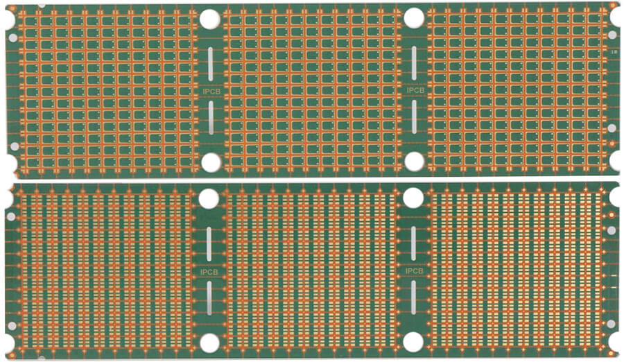
2.1 Basic characteristics of PCB
A PCB is composed of a series of lamination, wiring and prepreg treatments on the vertical stack. In a multi-layer PCB, the designer will lay out the signal lines on the outermost layer in order to facilitate debugging.
The wiring on the PCB has impedance, capacitance and inductance characteristics.
Impedance: The impedance of the wiring is determined by the weight of the copper and the cross-sectional area. For example, one ounce of copper has O. 49 mΩ/impedance per unit area. Capacitance: The capacitance of the wiring is determined by the insulator (EoEr), the reach of the current (A), and the line spacing (h). Expressed by the equation as C=EoErA/h, Eo is the dielectric constant of free space (8.854 pF/m), and Er is the relative dielectric constant of the PCB substrate (4.7 in FR4 rolling).
Inductance: The inductance of the wiring is evenly distributed in the wiring, about 1 nH/m.
For 1 ounce copper wire, in O.D. In the case of 25 mm (10 mil) thick FR4 rolling, the 0.5 mm (20 mil) wide and 20 mm (800 mil) long wire above the ground layer can produce 9.8 m∧ impedance, 20 nH The inductance and the coupling capacitance of 1.66 pF with the ground. Comparing the above values with the parasitic effects of the components, these are negligible, but the sum of all wiring may exceed the parasitic effects. Therefore, the designer must take this into consideration. General guidelines for PCB wiring:
(1) Increase the spacing of the traces to reduce the crosstalk of capacitive coupling;
(2) Lay the power line and the ground line in parallel to optimize the PCB capacitance;
(3) Route sensitive high-frequency lines away from high-noise power lines;
(4) Widen the power line and the ground line to reduce the impedance of the power line and the ground line.
2.2 Division
segmentation refers to the use of physical segmentation to reduce the coupling between different types of lines, especially through power lines and ground lines.
An example of dividing 4 different types of circuits using the division technique. On the ground plane, non-metallic trenches are used to isolate the four ground planes. L and C are used as filters for each part of the board. Reduce the coupling between the power planes of different circuits. High-speed digital circuits are required to be placed at the power entrance due to their higher instantaneous power demand. Interface circuits may require electrostatic discharge (ESD) and transient suppression devices or circuits. For L and C, it is better to use different values of L and C, rather than one big L and C, because it can provide different filtering characteristics for different circuits.
2.3 Decoupling between local power supply and IC
Local decoupling can reduce noise propagation along the mains of the power supply. The large-capacity bypass capacitor connected between the power input port and the PCB acts as a low-frequency ripple filter and at the same time as a potential reservoir to meet sudden power demand. In addition, there should be decoupling capacitors between the power supply and ground of each IC. These decoupling capacitors should be as close as possible to the pins. This will help filter out the switching noise of the IC.
2.4 Grounding technology
grounding technology is applied to both multilayer PCBs and single-layer PCBs. The goal of grounding technology is to minimize ground impedance, thereby reducing the potential of the ground loop from the circuit back to the power source.
(1) Ground wire of single-layer PCB
In a single-layer (single-sided) PCB, the width of the ground wire should be as wide as possible, and should be at least 1.5 mm (60 mil). Since star wiring cannot be implemented on a single-layer PCB, the change in jumper and ground wire width should be kept to a minimum, otherwise it will cause changes in line impedance and inductance.
(2) Ground wire of double-layer PCB
In the double-layer (double-sided) PCB, ground grid/dot matrix wiring is preferred for digital circuits. This wiring method can reduce ground impedance, ground loops and signal loops. Like in a single-layer PCB, the width of the ground and power lines should be at least 1.5 mm. Another layout is to put the ground plane on one side and the signal and power lines on the other side. In this arrangement, the ground loop and impedance will be further reduced, and the decoupling capacitor can be placed as close as possible between the IC power supply line and the ground layer.
(3) Protective ring
The protection ring is a grounding technology that can isolate a noisy environment (such as radio frequency current) outside the ring. This is because no current flows through the protection ring in normal operation.
(4) PCB capacitance
On a multilayer board, PCB capacitance is generated by a thin insulating layer separating the power supply surface and the ground. On a single-layer board, the parallel arrangement of the power line and the ground line will also cause this capacitive effect. One advantage of the PCB capacitor is that it has a very high frequency response and a low series inductance evenly distributed over the entire surface or the entire line. It is equivalent to a decoupling capacitor evenly distributed across the board. No single discrete component has this feature.
(5) High-speed circuit and low-speed circuit
High-speed circuits should be placed closer to the ground plane, and low-speed circuits should be placed closer to the power plane.
(6) Copper filling of ground
In some analog circuits, the unused circuit board area is covered by a large ground plane to provide shielding and increase decoupling capabilities. But if the copper area is suspended (for example, it is not connected to the ground), then it may behave as an antenna and will cause electromagnetic compatibility problems.
(7) Ground plane and power plane in multilayer PCB
In a multilayer PCB, it is recommended to place the power plane and the ground plane in adjacent layers as close as possible to generate a large PCB capacitance on the entire board. The fastest critical signals should be close to one side of the ground plane, and non-critical signals should be placed close to the power plane.
(8) Power requirements
When the circuit requires more than one power supply, use grounding to separate each power supply. But it is impossible to ground multiple points in a single-layer PCB. One solution is to separate the power cord and ground wire from one power supply from other power cords and ground wires. This also helps to avoid noise coupling between power supplies.
3 Concluding remarks
The various methods and techniques introduced in this article are conducive to improving the EMC characteristics of the PCB. Of course, these are only part of the EMC design. Usually, reflection noise, radiation emission noise, and interference caused by other process technical issues must be considered. In the actual design, according to the target requirements and design conditions of the design, reasonable anti-electromagnetic interference measures should be adopted to design a PCB circuit board with good EMC performance.