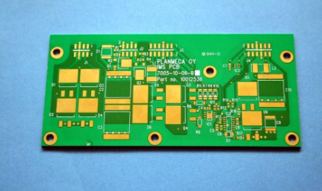
The role of PCB schematics and common problems in circuit board design

1. The role of PCB schematic diagram
PCB schematic diagrams can be reversed based on PCB file diagrams through PCB copy board technology or directly based on the actual product. It can also be forward-designed by electronic engineers according to customer needs. But whether it is used to analyze circuit board principles and product operating characteristics in reverse research, or is reused as the basis and basis for PCB design in forward design, PCB schematics have a special role. Moreover, it plays an indispensable role in the process of product design, debugging, maintenance and improvement.
PCB board reverse schematic production is a subdivision of PCB copy service items. Generally, only a sample or PCB file is required to derive the schematic diagram of the PCB template or PCB file. Among the many PCB copy board/design companies in Shenzhen, we first recommend Shenzhen Century Chip Integrated Circuit Co., Ltd. The company is a well-known reverse technology research institution integrating R&D, design, manufacturing, technology and services. Since the establishment of the initial team, it has been focusing on conducting business based on the research results of reverse engineering technology of electronic products. Rely on reverse technology research to provide customers with product technical services and system-level solutions to help customers achieve the maximum cost-effectiveness of their products. The reversed schematic diagrams have been strictly network proofed with the PCB. The component position numbers, model numbers, network names, etc. in the diagrams are complete and clear and easy to check, and the "modular" drawing method of "relatively concentrated functional module related components" is adopted., Its readability is comparable to the original design. Customers can easily grasp the design ideas of the product, capture the shining points of some high-end designs, and use them for their own purposes, or easily integrate their own unique designs to develop higher-end products.
2. Common problems in PCB schematic design
Below, Century Core mainly answers common questions in PCB schematic design for everyone, and hope to help you, especially the problems often encountered when using CAD software for small circuit design for the first time.
Question 1: What is the difference between part description and part identification?
Answer: The part description (Library Reference) is the name of the part in the parts library. It takes a common name for the parts with the same shape and pin function; the part identification is the name designed by the user according to the needs in the circuit diagram, and of course it cannot be random. Pick. Under normal circumstances, they can be collectively referred to as part names without subdividing them.
Question 2: What is the use of Part Fields and Read Only Fields in the part properties dialog box?
Answer: The Part Fields in the part properties dialog box has two functions. For general parts, you can mark the parameters of the part in these settings; for simulated parts, you can set the model parameters related to the simulation in these settings. Read Only Fields are generally used for the definition of simulation models in simulated parts.
Question 3: How to directly replace parts?
Answer: Double-click on the part to be replaced, enter the new part description in Lib Ref in the part properties dialog box that pops up, and click the OK button to complete the direct replacement of the part.
Question 4: How to set the default part package of common parts?
Answer: You can use the part library editor to open the part to be modified, and enter the package name of the part in Part Foot Print 1 in the Designator tab of the part description (Deion) dialog box. This part package name is the default part package of the part.
Question 5: How to switch directly from the schematic to the PCB design?
Answer: Click the menu Design\Update PCB command to automatically switch from the schematic to the PCB design. But pay attention to open the PCB diagram that needs to be switched, and close other irrelevant PCB diagrams, otherwise unexpected problems will occur.
Question 6: What should I do if the schematic cannot be printed?
Answer: The schematic can’t be printed, and you can solve it as follows: modify the default printer; check whether the printer's paper settings are appropriate; the printer is not compatible. Question 7: What should I do if the system cannot recognize the parts library?
Answer: The system cannot recognize the parts library. You can try the following solutions: reinstall the printer driver. If there is no printer, you can install a printer driver at will; sometimes after installing some software, the system may not recognize the parts library. In that case, you can reinstall the Protel program.
Question 8: How to modify the properties of parts in batches?
Answer: Click the Globe button in the part attribute dialog box, you can set the overall modification options in the overall modification dialog box, and enter the relevant replacement settings in Copy Attributes. For example, {A*=B*}, then the identifier beginning with A should be Identification symbols beginning with B.