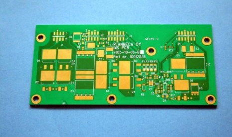
The second method of dealing with the conventional problems of PCB board

1. The problem of holes
1. During the drilling design process of the PCB circuit board, do not have heavy holes in the drilling diagram; if it does, we will delete the overlapping small holes or the same large holes by default.
2. If there is not enough NPTH in the board for processing positioning holes, it is recommended that engineers add NPTH holes on the auxiliary side, but do not affect the SMT reference point.
3. If it is not necessary, do not have a design with a large PTH orifice disk and aperture. We may regard this as an abnormality, and it is recommended that design engineers try to avoid it unless it is necessary.
Second, the solder mask problem
1. Do not open the window for non-metallized hole solder mask. Generally, the distance from the wire is 2.5mil or more; otherwise, we will modify the window of the non-metallized hole by default to ensure that the wire does not expose copper. When the non-metalized hole file is not windowed, we will increase the window size larger than 6-10 mils on each side of the hole diameter.
2. If there is a golden finger design, the window needs to be opened full, not a single window; otherwise, we will modify it to full window by default.
3. If the top of the gold finger is too close to the nearby pad, and the solder mask between the gold finger window and the pad window is less than 0.5mm, we will cover the top of the gold finger by default to meet the solder mask bridge. It is 0.5mm.
4. When there is only one solder mask file in the PCB file, and there are only plug-in through holes in the board, and no SMT pads, we regard the solder mask image as the front and back.
Three, character and mark issues
1) Engineers should not design off-board characters, otherwise, we will delete them by default, unless a large number of off-board characters appear; we will move inward characters on the edges of the board.
2) Engineers should not design overlapping characters, and keep the distance between characters as far as possible; partial overlapping characters are shifted by default, and for large-area overlapping characters, we can only return to the engineer to request redesign and output.
3) The characters should avoid vias and NPTH holes as much as possible, and should not be located at or near component hole pads and SMT pads.
The above is an introduction to the processing methods of the conventional problems of PCB boards. Ipcb is also provided to PCB manufacturers and PCB manufacturing technology.