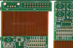
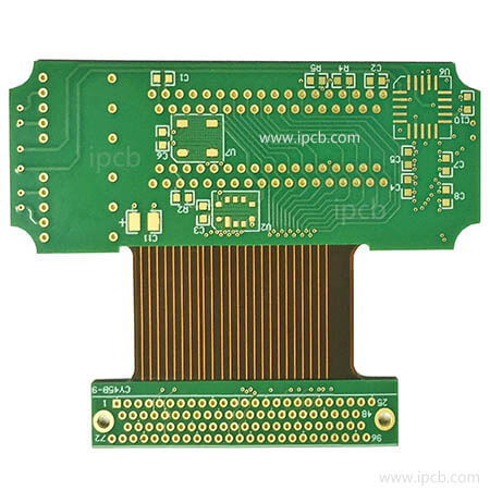
Flexible circuit boards and hard circuit boards are combined through pressing and other processes according to relevant process requirements to form a circuit board with FPC and PCB characteristics.
The Rigid-flex PCB is widely used, such as high-end smartphones such as iPhones; High-end Bluetooth earphones (with requirements for signal transmission distance); Intelligent wearable devices; robots; UAV; Curved displays; High-end industrial control equipment; It can be seen in fields such as computers and LCD screens, motherboards and displays, aerospace and satellites.

Rigid-Flex PCB
The advantages of Rigid-flex PCB
Featuring excellent features in both PCB and FPC, it can be folded, bent, reduced space, and welded to complex components. Compared to flat wires, it has a longer lifespan, more reliable stability, and is not easy to break, oxidize, or fall off. It is very helpful for improving product performance.
1. Small size and flexible design
The Rigid-flex PCB makes it easier to install more components in a smaller space, as they can change shape according to specific contours. This technology will reduce the size and weight of the final product, as well as the overall system cost. At the same time, the compact shape of the Rigid-flex PCB makes it the best choice for thin wire and high-density circuits in HDI technology.
2. Customizable for different applications
The Rigid-flex PCB package has free geometric shape and can be customized for applications in many industries, such as aerospace, military, medical equipment and consumer electronics. They can be customized in size and shape to adapt to shell design and 3D design, providing designers with more possibilities to meet different requirements in specific applications.
3. Better mechanical stability
The stability of the rigid board and the flexibility of the flexible board form a stable structure for the entire package while retaining the electrical connection reliability and flexibility required for small-space installation.
4. Better performance in harsh environments
Rigid-flex PCBs have high impact resistance and vibration resistance, so they can work normally in high stress environments. Fewer cables and connectors are used in Rigid-flexPCBs, which also reduces safety risks and maintenance in future use.
5. Easy to manufacture and test
Rigid-flex PCB requires a smaller number of interconnectors and related components/parts. It helps to simplify assembly operations and make Rigid-flex PCBs easier to assemble and test. The Rigid-flex PCB is very suitable for PCB prototypes.
How to Design a Rigid-flex PCB?
Traditional Rigid-flex PCB include external hard circuit board material layers and sandwich soft board stacking layers. PTH endpoints are used for interlayer interconnection and connection of internal circuits to external hard areas. These hard surfaces only have simple pads and no conductor configurations or other conductive areas, as their purpose is to protect all circuits from connections, short circuits, and damage caused by assembly.
1. Design requirements for flexible area lines
Use a teardrop shape between the thick and thin lines of the line to prevent sudden expansion or contraction of the line; Use rounded corners to avoid sharp corners.
2. When meeting electrical requirements, the maximum value of the solder pad should be taken. The transition line at the connection between the solder pad and the conductor should avoid right angles and be smooth. Toes should be added to the independent solder pad to enhance support.
3. Dimensional stability, with the design of adding copper as much as possible, and designing as many solid copper berths as possible in the waste area.
4. Design of Cover Film Window
Add manual alignment holes to improve alignment accuracy. Window design considers the range of adhesive flow, and usually the window opening is larger than the original design. The specific size is provided by ME as a design standard. Small and dense window openings can be designed with special molds such as rotary punching and skip punching.
5. Design of Soft Hard Transition Zone
The smooth transition of the line should be perpendicular to the direction of the curve; The wires should be evenly distributed throughout the entire bending area; The wire width should be maximized throughout the entire bending zone, and the transition zone should not use PTH design Coverlay or No flow PP design as much as possible.
6. Design of flexible zones with air gap requirements
There should be no through holes in the parts that need to be bent. Add protective copper wires on both sides of the line. If there is insufficient space, additional protective copper wires can be added at the inner R corner of the bent section. The connecting part of the circuit needs to be designed as an arc. The larger the bending area, the better, without affecting assembly.
The Rigid-flex PCB is made in a sheet-like pattern, and the soft board cutting treatment is only carried out when both the hard and soft areas are completed. Before this stage, the layered dielectric passes through the manufacturing process together, and the designer can assume that all layers have equal support. For any soft board manufacturing process, a mechanical layout will be established to construct all endpoints with precise dimensions, and the circuit list will be reorganized based on the circuit type and configured with graphics to determine the overall form of the soft board, set design guidelines, and wiring. At the same time, some additional matters will be noted, including confirming the appearance of the FPC and PCB, special tool slots, window openings and bevels, determining the soft board area, single or double sided, attached or not attached Material selection and specifications.
The soft board area should have a vertical relationship with the PCB area after forming, and the edges of the hard area should be rounded or protected to protect the soft board from tearing or cutting damage. The specifications and requirements of materials and structures should be as open as possible, instead of defining narrow dielectric, adhesive selection and thickness, ready-made specifications can be used. The conductor layer should be matched with the electrical requirements as much as possible to maintain consistency. thicker circuits require thicker adhesive layers, which will reduce the performance of heat dissipation.
Rigid-flex PCB is a new type of printed circuit board that combines the durability of a rigid PCB with the adaptability of a flexible PCB. The finished product is small in size and light in weight, and can meet the requirements of three-dimensional assembly. It meets the demand for consumer electronic products and has huge market potential.