1. Brief introduction of printing machine
Tin brushing is a very important link in the entire SMT process. This link includes the quality control of the solder paste and the use of the printing machine.
2. Introduction to the placement machine
Mounting technology is the key to the assembly of SMT products. Therefore, the placement machine is the core and key equipment in the assembly line of SMT products. It determines the most difficult thing in the SMT process. There are two process requirements for the placement process:
(1) High placement accuracy (determined by the placement machine accuracy and related performance)
(2) The placement rate is high (the placement rate of a high-performance placement machine should be controlled above 99.98%)
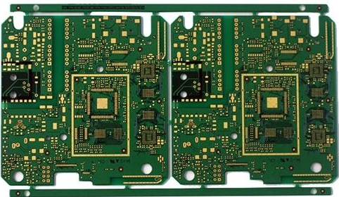
The placement machine is a computer-controlled high-precision automation equipment integrating light, electricity, gas and machinery. It quickly and accurately attaches the SMC/SMD to the designated pad position on the PCB through functions such as picking, displacement, alignment, and placement. Because the quality of the placement will affect the welding effect, this requires a relatively high placement accuracy, and we also need high efficiency, all of which place relatively high requirements on the placement machine.
JUKI patch production line
1. A brief introduction to the JUKI machine:

At present, there are a large number of JUKI machines in our domestic sales factories, with better performance, lower failure rate, and simpler operation. New operators can operate independently in a short period of time. Except for the JUKI machine FX-1R model, which has two placement heads, all other JUKI machines have only one placement head.
Warning icon on the machine:
In order to prevent the operator of the machine from personal injury or damage to other objects and the machine when operating the machine, please strictly abide by the safety operation regulations! When the machine is running, it is forbidden to put your hands and head into the machine. When returning to the origin or starting normal operation, please check whether there is any sundries in the machine that hinder the operation of the placement head. When replacing the loading and unloading feeder, it must be done when the machine has stopped running and the safety door is opened. At the position where the warning signs are affixed, pay attention to the signs and strictly follow the signs and warnings. Don't make it convenient for a while and cause unnecessary damage to the person or the machine due to illegal operation.
2. A brief introduction to YAMAHA machine:
We have purchased a lot of YAMAHA models, and their placement speed is faster, but the operation is a bit more complicated than the JUKI machine. Its YG200 model has four placement heads, which are divided into four desktops: A, B, C, and D. Each placement head is equipped with six nozzles; while YV100Xg has only one placement head, but it can be equipped with eight nozzles
Among them, 2, 4, 6, 8 are flying nozzles, which can be automatically changed during operation according to the needs. The 3 types of nozzles (71, 72, 73) that can be replaced by themselves are in our YAMAHA placement machine, YG200 There are input and operation parts on the front and back, while the YV100xg has only one-sided input and operation parts. The operation panel buttons are equipped on the front and back of the host, and frequently used commands can be executed on the operation panel. When each button is ON, the indicator light turns on.
Functions of the buttons on the operation panel:
ACTIVE: Buttons used in order to make other buttons on the panel effective
READY releases the emergency stop and turns the servo on
RESET stops operation and returns to the preparation state of substrate production
START performs component placement based on board data
STOP interrupts the operation of the machine (use the START button to restart the machine) ERROR CLEAR clears the alarm buzzer and alarm screen when an error occurs EMERGENCY STOP Press this button, the machine is in an emergency stop state, and rotate to the right when it is to be released.
In order to operate and use YAMAHA machines safely and correctly, operators must strictly abide by the safety precautions described in this booklet and obey relevant instructions. Because this book cannot detail all relevant safety content and details, the operator's degree of importance and judgment on safety has become an important factor in ensuring safety.
1. During the operation of the machine, it is absolutely forbidden to extend the body or part of the body (hands, head) into the operating range of the machine. At the same time, it is absolutely forbidden to extend other objects into the operating range of the machine by hand.
2. It is strictly forbidden for two persons to operate the machine at the same time.
3. When the materials in the machine production process are used up to replace the materials, the safety cover of the machine must be opened.
4. For warning signs affixed to the machine, it must be confirmed that the contents of the signs and the instructions in the signs are unconditionally obeyed.
3. Introduction to reflow soldering
Reflow soldering (Reflow soldring), by remelting the solder paste pre-distributed on the printed board pads, to achieve mechanical and electrical connection between the solder ends or pins of the surface mount components and the printed board pads Soft soldering. Reflow soldering is the key core technology of surface assembly technology. The quality of the soldering process not only affects normal production, but also affects the quality and reliability of the final product. The soldering temperature curve in reflow soldering refers to the curve of the temperature at the test point changing with time. According to the role of each section of the soldering process, it is generally divided into four sections: preheating zone, constant temperature zone, reflow zone and cooling zone.
At present, our domestic sales factories use these two welding furnaces. The following is a general introduction to the soldering principle: when the PCB enters the preheating zone, the solvent and gas in the solder paste evaporate, the solder paste softens, collapses, and covers the pads, isolating the pads and component solder ends from oxygen; the PCB enters a constant temperature During the zone, the PCB and components are fully preheated to prevent the PCB from suddenly entering the soldering high temperature zone and damaging the PCB and components; in the flux activation zone, the flux in the solder paste wets the pads and component solder ends, And clean the oxide layer; when the PCB enters the reflow area, the temperature rises rapidly to make the solder paste reach a molten state, and the liquid solder wets the PCB pads and component solder ends, and at the same time diffuses, dissolves, metallurgical bonding, flooding or reflow mixing to form solder Joints; PCB enters the cooling zone and solidifies the solder joints. At this point, the entire welding is completed.