1. Brief introduction
Electronic product manufacturing process In view of the technological development and job requirements of electronic product manufacturing enterprises, it focuses on describing several main links in the electronic product manufacturing process: assembly, welding, debugging and quality control, and introduces in detail the basics that electronic manufacturing skilled talents should master Knowledge; debugging and use of printing, patching, soldering (including current hotspot lead-free soldering), inspection technology and related tools (such as ICT, AOI, BGA ball implanter, etc.) in SMT process; anti-static in the production process Questions; knowledge and methods that inspectors should be familiar with; knowledge of writing process documents and managing technical files as craftsmen; participating in various certifications for exporting products of enterprises, etc.
2. Introduction to Electronic Process Technology
(1) It mainly introduces the basic knowledge of electronic process technology. In the research of electronic product manufacturing process, the elements of materials, equipment methods, operators and managers are the basic characteristics of electronic process, usually "4m+m" To simplify the basic elements of the electronic product manufacturing process.
(2) Understand that electronic technology has the characteristics of involving many scientific and technological fields, its formation time is relatively late and rapid development, and the development status of my country's electronic industry and its weak links.
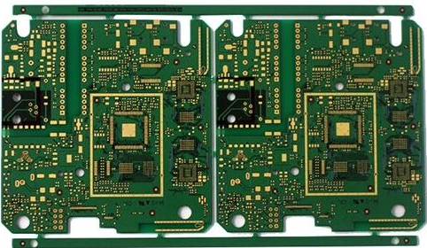
(3) Familiar with the knowledge of electronic product process operation safety, understand the basic process of circuit board production in electronic products as follows:
1. Production equipment 2. Automatic placement 3. Reflow soldering 4. Automatic plug-in 5. Manual plug-in 6. Wave soldering (dip soldering) 7. Manual repair soldering 8. Repair 9. Inspection and testing 10. Packaging

Third, understand electronic components from the perspective of process
Generally speaking, in the electronics industry, components refer to passive components such as resistors, capacitors, inductors, connectors, and switches; devices refer to active components such as transistors and integrated circuits. However, in actual work, the two are not strictly distinguished, and they can be collectively referred to as electronic components.
(1). Familiarize yourself with the model naming and labeling methods of electronic components through the study of this chapter. Usually the names of electronic components reflect their types, materials, characteristics, models, production serial numbers and distinguishing codes, and can indicate the main electrical parameters. The names of electronic components consist of letters and numbers. The model and various parameters should be marked on the surface of the components as much as possible. There are three commonly used labeling methods:
Direct standard method:
The main parameters of the components are printed directly on the surface of the components, that is, the direct marking method. This method is intuitive and can only be used for larger components. For example: RXYC-50-T-1K5-+10% (-10%) is printed on the surface of the resistor, indicating that the type is moisture-resistant glaze wire wound adjustable resistor, with a rated power of 50W and a resistance of 1.5 kiloohms, The allowable deviation is plus or minus 10%.
Text symbol method:
It is mainly used to mark semiconductor devices, and users indicate that their types and related parameters should conform to national standards. For example: 3DG6C represents the domestic NPN type low-power transistor with silicon material, the model number is 6, and C represents the withstand voltage specification.
1. This method uses the symbol R or Ω for Ω, K for KΩ, and M for MΩ. The integer part of the resistance value (Arabic numerals) is written in front of the symbol, and the decimal part is written in the back 2 of the symbol. Digital representation. The method of using three digits to indicate the resistance value and corresponding letters to indicate the allowable deviation is called digital representation. Among them, the numbers are in order from left to right, the first and second digits are the effective value of the resistance, and the third digit is the number of zeros. The unit of resistance is Ω. For example: the nominal resistance of 102J is 10*102=1KΩ, J indicates that the allowable error of the resistance is ±5%.
Color code method:
Color circles of different colors are used to indicate the marking method of the nominal resistance value and the allowable deviation of the resistor. This method of representation is often used on small resistors. There are two commonly used color standard methods, four-color standard method and five-color standard method.
(2) Comprehensively understand the structure and characteristics of various electronic components, learn to choose the correct application; understand the classification of plug-ins and the main parameters and types of commonly used plug-ins and switches; understand the hazards of static electricity to components and electrostatic protection measures.
4. Commonly used materials and tools for manufacturing electronic products
(1) Through learning, let me understand the performance, parameters and characteristics of wires and insulating materials, and master the correct selection and installation of wires should pay attention to:
1. Safe current carrying capacity 2. Highest withstand voltage and insulation performance 3. Wire color 4. Working environment 5. Easy connection operation
(2). Grasp the properties, composition, principle of action and selection of solder and flux; use soldering tools correctly.
Flux is usually a mixture of rosin as the main component, which is an auxiliary material to ensure the smooth progress of the soldering process. The main function of the flux is to remove the oxides on the surface of the solder and the base metal (material) to be soldered, so that the metal surface can achieve the necessary cleanliness. It prevents the surface from re-oxidation during soldering, reduces the surface tension of the solder, and improves the soldering performance. The quality of performance directly affects the quality of electronic products.
5. Surface Mount Technology (SMT)
(1) Through this chapter, I learned about the development history and characteristics of surface mount technology; I learned about the types, specifications and characteristics of SMT components, SMT integrated circuits.
(2), master the SMT printing (2) (2) board-making wave soldering process flow:
1. Making adhesive 2. Screening missed adhesive 3. Mounting SMT components 4. Curing adhesive 5. Inserting THT components 6. Wave soldering 7. Printed board (cleaning) test
(3) Master the reflow soldering process flow of SMT printed boards:
Printed board assembly and welding use reflow soldering process. One of the typical methods of applying solder is to use screen printing solder paste. The reflow soldering process of screen printing solder paste:
1. Making solder paste screen 2. The screen is missing solder paste 3. Mounting SMT components 4. Reflow soldering 5. Printed board cleaning and testing
(4) The typical equipment familiar with the assembly and soldering of SMT circuit boards is the structure of solder paste printer, placement machine and reflow soldering furnace. Understand SMT process quality analysis.