Cause analysis and Improvement Countermeasures of poor welding of OSP surface-treatedPCB
OSP is a process for surface treatment of copper foil of printed circuit board, which meets the requirements of the RoHS directive.
1. Introduction PCB is an indispensable material for modern electronic products. With the rapid development of Surface Mount Technology (SMT) and integrated circuit (IC) technology, PCB needs to meet the development requirements of high density, high flatness, high reliability, smaller aperture, and smaller pad, and the requirements for PCB surface treatment and manufacturing environment are becoming higher and higher. OSP surface treatment is a common PCB surface treatment technology at present. It is to grow a layer of 0.2 ~ 0.5um organic film on the clean bare copper surface by chemical method. This film has oxidation resistance, heat shock resistance, and moisture resistance at room temperature, and can protect the copper surface from oxidation or vulcanization. In the subsequent high-temperature welding, The protective film must be easily and quickly removed by the flux to expose the clean copper surface and combine with the molten solder to form a solid solder joint in a very short time.
Compared with other surface treatments, OSP surface treatment has the following advantages and disadvantages: A. OSP surface is flat and uniform, and the film thickness is 0.2 ~ 0.5um, which is suitable for PCB of SMT closely spaced components; b. OSP film has good thermal shock resistance, is suitable for lead-free process and single and double-sided board processing, and is compatible with any solder; c. In the water-soluble operation, the temperature can be controlled below 80 degree Celsius, which will not cause the problem of substrate bending and deformation; d. Good operating environment, less pollution, easy to automate the production line; e. The process is relatively simple, with high yield and low cost; f. The disadvantage is that the protective film formed is very thin, and the OSP film is easy to scratch (or scratch); g. After multiple high-temperature welding of PCB, OSP film (referring to OSP film on unwelded pad) will change color, crack, thin, and oxidize, affecting solderability and reliability; h. There are many kinds of potions, different properties, uneven quality, and so on.
2. Problem description in the actual production process, OSP PCB board is prone to surface discoloration, uneven film thickness, out of tolerance (too thick or too thin), and other problems; In the later stage of PCB production, if the formed PCB is stored and used improperly, it is prone to welding problems such as pad oxidation, poor tin on the pad, unable to form solid solder joints, false soldering, and insufficient solder; When SMT produces the second side of the double-sided plate and tin furnace welding, it is easy to have problems such as poor reflow welding, copper leakage at solder joints, appearance can not meet ipc3 standard, and high rate of tin furnace welding defects.

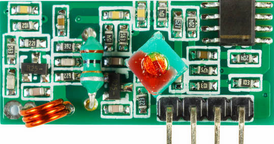
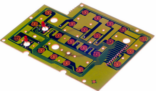
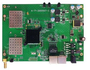
3. Case analysis: when an OSP surface-treated PCB product of a company is produced on the first side of SMT, the tin on the component pad is good, when producing the second side, the tin on the connector after passing through the furnace and the component pad at some positions is poor, and the solder has some problems of anti wetting and solder refusal on the pad, as shown in Figure 1 below. The PCB in this case is an OSP surface treatment method, and the SMT process is a lead-free process. According to the analysis of basic welding principles and practical engineering experience, the occurrence of solder rejection and anti-wetting is directly related to the solderability of PCB surface pads. Therefore, the analysis idea of this case is to find out the causes of poor solderability of OSP and give corresponding improvement countermeasures by means of appearance inspection, cleaning bad pads with isopropyl alcohol (IPA), and hydrochloric acid, and then using EDs for component analysis in a third-party laboratory.
1 Poor tin coating
3.1 analysis process a. observing the defective products with a microscope, it is found that there is much poor wetting on PCBA, the poor wetting pad is a spherical and irregular network, and the PCB pad presents a clear non solderable morphology, as shown in Figure 1 above.
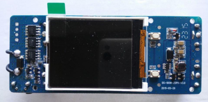
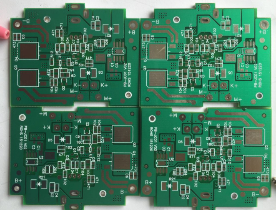
b. Clean the solder pad with isopropyl alcohol (IPA) and immerse it in a 255oc tin bath for 5 seconds. Verification purpose: in case of nonwetting caused by foreign matter pollution, tin can be wetted after IPA cleaning. Conclusion: IPA cleaning is not conducive to tin on the pad, indicating that the failure of tin on the pad is not caused by foreign matter coverage [3], as shown in Figure 2.
2 Comparison of tin on the pad before and after IPA cleaning
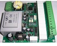
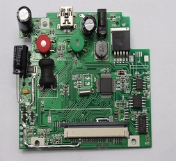
c. Clean the solder pad with poor wetting with hydrochloric acid and immerse it in a 255oc tin bath for 5 seconds. Verification purpose: in case of nonwetting caused by pad oxidation, tin can be wetted after hydrochloric acid cleaning. Conclusion: the solder is well wetted after cleaning with hydrochloric acid, which indicates that there are metal oxides on the surface of the nonwetted pad, which makes the solder unable to be wetted during the welding process [3].
3 Comparison of tin on the pad before and after hydrochloric acid cleaning
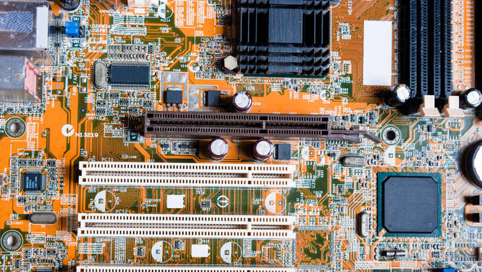
d. EDS analysis shall be carried out for the welding refusal position. Verification purpose: analyze the elemental composition of the poor position on the surface of the solder pad to determine the root cause of poor tin application. Conclusion: Copper in the area without solder pad is absolutely dominant, indicating that it is not covered by solder and there is no other metal pollution; There are carbon, oxygen, and other elements in the solder edge area of the rejected welding area, which is caused by the influence of the welding process and the composition in the air [3], as shown in Figure 4.
4 EDS analysis of the bad position
e.PCB solderability test. According to the method of test A1 in IPC j-std-003b, the solderability test shall be carried out after simulating one reflow soldering of the PCB optical board and optical board in the same cycle. Verification purpose: compare the solderability of PCB between the smooth plate and simulated primary reflow furnace. Conclusion: the tin on the solder pad of the same cycle PCB light plate is good, and the appearance meets the IPC requirements, as shown in Figure 5; After one reflow, the OSP film deteriorated and thinned, the solderability of PCB became poor, and some pads were poorly wetted, as shown in Figure 6.
4.1 Improvement measure 4.1 select appropriate OSP potion. There are three types of OSP materials: rosin, active resin, and azole. At present, the most widely used is oxazole OSP. Oxazole OSP has been improved for about 6 generations, and now the decomposition temperature can be as high as 354.9 degree Celsius [4,5], which is suitable for lead-free process and multiple reflow soldering. Before PCB production, appropriate liquid medicine shall be selected according to the production process of the product.
4.2 during PCB production, the thickness and uniformity of OSP film shall be strictly controlled. The key to the OSP process is to control the thickness of the protective film. The film thickness is too thin and the thermal shock resistance is poor. During reflow welding, the film can not withstand high temperature, cracking, and thinning, which is easy to cause pad oxidation and affect solderability; If the film thickness is too thick, it can not be well dissolved and removed by flux during welding, which will also lead to poor welding.
4.2.1 production process flow of OSP board: plate discharge - oil removal - water washing - micro corrosion - water washing - prepreg - DI water washing - drying - upper protective film (OSP) - drying - DI water washing - drying - drying - drying - drying - plate receiving
4.2.2 main factors affecting OSP film thickness A. oil removal. The degreasing effect directly affects the film-forming quality. If the oil removal is poor, the film-forming thickness is uneven. On the one hand, the concentration can be controlled within the process range by analyzing the solution. On the other hand, check whether the degreasing effect is good. If the degreasing effect is not good, replace the degreasing fluid in time.
b. Micro erosion. The purpose of micro etching is to form a rough copper surface for film formation. The thickness of micro etching directly affects the film-forming rate. In order to form a stable film thickness, it is necessary to maintain the stability of micro etching thickness. Generally, it is appropriate to control the micro etching thickness at 1.0 ~ 1.5um. Before each shift of production, it is necessary to measure the micro etching rate and determine the micro etching time according to the micro etching rate.
c. Prepreg. Prepreg can prevent harmful ions such as chloride ions from damaging the OSP cylinder solution. The main function of the OSP prepreg cylinder is to accelerate the formation of OSP film thickness and deal with the influence of other harmful ions on OSP cylinder. There is an appropriate amount of copper ion in the prepreg solution, which can promote the formation of the complex protective film and shorten the dip-coating time. It is generally believed that alkylbenzimidazole has been complexed with copper ion to a certain extent in pre flux solution due to the existence of copper ion. When the complex with a certain degree of aggregation is deposited on the surface of copper to form a complex film, it can form a thicker protective layer in a short time, so it plays the role of the complex accelerator. If the content of alkylbenzimidazole or similar components (imidazole) in the prepreg is very small, when the copper ion is excessive, the prepreg solution will age prematurely and need to be replaced. Therefore, it is necessary to focus on controlling the concentration and time of the prepreg.
d. Concentration of main components of OSP. Alkylbenzimidazole or similar components (imidazole) are the main components in OSP solution, and the concentration is the key to determine the film thickness of OSP. During the production process, the concentration of OSP solution needs to be monitored.
e. PH value of the solution. The stability of pH value has a great impact on the film-forming rate. In order to maintain the stability of pH value, a certain amount of buffer is added to the solution tank. Generally, if the pH value is controlled at 2.9 ~
3.1, a dense, uniform OSP film with moderate thickness can be obtained. When the pH value is high and pH > 5, the solubility of alkylbenzimidazole decreases and oil precipitates; When the pH value is low and pH < 2, the formed membrane will be partially dissolved. Therefore, it is necessary to focus on monitoring pH value.
f. Temperature of the solution. The change of temperature also has a great impact on the film-forming rate. The higher the temperature, the faster the film-forming rate. Therefore, it is necessary to control the temperature of OSP tank.
g. Film-forming time (dip-coating time). Under the determined OSP tank liquid composition, temperature, and pH value, the longer the film-forming time, the thicker the film-forming time. Therefore, it is necessary to control the film-forming time.
4.2.3 detection of OSP film thickness at present, most PCB factories use UV spectrometer to measure OSP film thickness. The principle is mainly to use the strong absorption characteristics of imidazole compounds in OSP film in the ultraviolet region, and then calculate the OSP film thickness by measuring the absorbance at the maximum. This method is simple and easy, but the test error is large. Another method is to use FIB technology to measure the actual thickness of OSP film [6]. PCB manufacturers need to use appropriate methods to detect and control the thickness of OSP film during production to ensure that the thickness of OSP film meets the standard requirements.
4.3 packaging and storage requirements of OSP board due to the extremely thin OSP film, if exposed to high temperature and humidity for a long time, the PCB surface will be oxidized and the solderability will become poor. After the reflow soldering process, the OSP on the PCB surface will also be cracked and thinned, which is easy to leads to the oxidation of PCB copper foil and poor solderability.
4.3.1 OSP board packaging requirements: the incoming materials of the OSP Board shall be vacuum packaged and attached with a desiccant and humidity display card. Isolation paper shall be used between PCB boards to avoid scratching or friction damage to OSP film.
4.3.2 the OSP Board shall not be directly exposed to sunlight. It shall be stored in an environment with a relative humidity of 30 ~ 70% and temperature of 15 ~ 30 degree Celsius for less than 6 months. It is recommended to use a special moisture-proof cabinet for storage. If the PCB is damp or expired and cannot be baked, it can only be returned to the PCB Factory for OSP rework.
4.4. Use and precautions of OSP board in SMT section A. before opening the PCB, check whether the PCB package is damaged and whether the humidity display card is discolored. If it is damaged or discolored, it cannot be used. Online production is required within 8 hours after unsealing. It is recommended to use as much as unsealed. PCB that is not finished or mantissa should be vacuum packed in time.
b. It is necessary to control the temperature and humidity of the SMT workshop. It is recommended that the workshop temperature: be 25 ± 3 degree Celsius, humidity: be 50 ± 10%. During the production process, it is forbidden to directly contact the PCB pad surface with bare hands to prevent sweat pollution, oxidation, and poor welding.
c. The PCB printed with solder paste shall be pasted as soon as possible, and the components shall pass through the furnace. Try to avoid plate washing caused by printing errors or mounting problems, because plate washing will damage the OSP film. If it is really necessary to wash the plate, it is not allowed to soak or clean it with a high volatile solvent. It is recommended to wipe the solder paste with non-woven fabric stained with 75% alcohol. The cleaned PCB shall be welded within 2 hours.
d. After the SMT single-sided patch is completed, the SMT components on the second side shall be installed within 24 hours, and the selective welding or wave soldering of dip (plug-in) components shall be completed within 36 hours at most.
e. Since the fluidity of the PCB with OSP surface treatment is worse than that of the PCB paste with other surface treatment, the solder joint is easy to expose the copper. The opening of the steel mesh can be appropriately increased in the design. It is recommended to open the hole according to the pad 1:1.05 or 1:1.1, but pay attention to the anti tin bead treatment of chip components.
f. When the peak temperature and reflow time of OSP board reflow meet the welding quality, it is recommended to deviate from the lower limit of the process window as far as possible, and the peak temperature and reflow time should be as low as possible; When producing double-sided board, it is recommended to appropriately lower the temperature of the first side (small component side) and set the temperature of both sides separately to reduce the damage of high temperature to OSP film. If possible, nitrogen production is recommended, which can effectively improve the poor oxidation welding of the second side pad of the double-sided OSP PCB board.
5. Conclusion there are many factors affecting the poor welding of OSP surface-treated PCB, such as the composition and quality of OSP potion, the thickness, and uniformity of OSP film, the packaging and storage of OSP board, the use and time control of SMT section, and the process parameters in the production process (such as steel mesh opening, furnace temperature, etc.). Among them, the quality of OSP solution and the thickness and uniformity of OSP film are the preconditions to ensure the welding quality. The welding defects caused by these PCB manufacturing problems are difficult or even impossible to solve through process methods in the SMT production process. Therefore, to improve and ensure good welding quality, the PCB factory needs to strictly control the key process parameters of PCB manufacturing, Ensure the quality of OSP film and PCB production quality; The PCB after production shall be packaged and stored in strict accordance with the requirements of OSP board; SMT shall be controlled in strict accordance with the use time; Control and optimize the process parameters such as steel mesh opening and furnace temperature, and formulate a perfect OSP PCB board production process.