When SMT is processed, it is inevitable that there will be some faults caused by material abnormalities, poor soldering, solder paste and other factors, but this kind of fault is relatively simple to deal with, just remove it and then solder it.
When SMT is processed, it is inevitable that there will be some faults caused by material abnormalities, poor soldering, solder paste and other factors, but this kind of fault is relatively simple to deal with, just remove it and then solder it. Then let's take a look at the desoldering techniques of SMT processing.
1. Desoldering skills for SMT processing
1. For components with few SMD components, such as resistors, capacitors, diodes, transistors, etc., first tin plating on one of the PCB pads on the PCB, and then use tweezers to hold the components to the mounting position and hold the circuit board with your left hand., Use a soldering iron to solder the pins on the tin-plated pad with your right hand. The left-hand tweezers can be loosened, and solder the remaining feet with tin wire instead. If you want to disassemble this kind of component, it is easy, just use a soldering iron to heat both ends of the component at the same time, and then gently lift the component after the tin is melted.
2. For SMT chip processing components with more pins and components with wider spacing, a similar method is adopted.

First, tin plate on one pad, and then use tweezers to clamp the component with the left hand to solder one foot OK, then use tin wire to solder the remaining feet. The disassembly of this type of component is generally better with a hot air gun. One hand holds the hot air gun to blow the solder, and the other hand uses tweezers and other fixtures to remove the component while the solder is melting.
3. For components with higher pin density, the soldering steps are similar, that is, solder one leg first, and then solder the remaining legs with tin wire. The number of pins is relatively large and dense, and the alignment of the pins and the pads is the key. Usually choose the soldering pads on the corners with only a small amount of tin plated. Use tweezers or hands to align the components with the soldering pads, and align the edges with pins. Press the components on the PCB with a little force, and solder them with a soldering iron. The corresponding pins of the disk are soldered well.
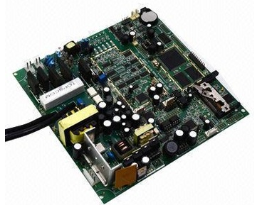
SMT processing
Second, the problems that need to be paid attention to when SMT processing
1. Joint standards for the development of electrostatic discharge control procedures. Including the design, establishment, implementation and maintenance of electrostatic discharge control procedures. According to the historical experience of certain military organizations and commercial organizations, it provides guidance for handling and protecting electrostatic discharge sensitive periods.
2. Semi-aqueous cleaning manual after welding. Including all aspects of semi-aqueous cleaning, including chemical, production residues, equipment, technology, process control, and environmental and safety considerations.
3. Desktop reference manual for through-hole solder joint evaluation. Detailed description of components, hole walls and welding surface coverage according to standard requirements, in addition to computer-generated 3D graphics. Covers tin filling, contact angle, tin dip, vertical filling, solder pad coverage, and numerous solder joint defects.
4. Template design guide. Provide guidelines for the design and manufacture of solder paste and surface mount adhesive coating templates. I also discussed template design using surface mount technology, and introduced the use of through-hole or flip-chip components? Kunhe technology, including overprinting, double printing and staged template design.
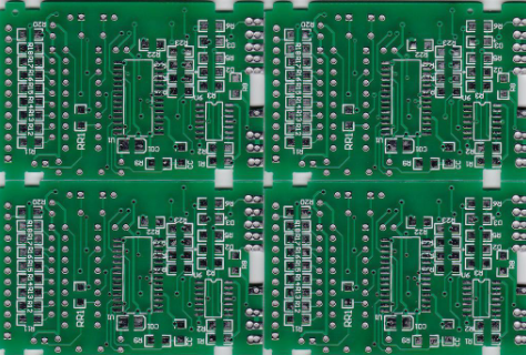
SMT patch processing, SMT patch processing plant, SMT patch, DIP plug-in processing plant, circuit board production
5. After the PCB is soldered, it becomes a water cleaning manual. Describe the cost of manufacturing residues, types and properties of aqueous cleaning agents, aqueous cleaning processes, equipment and techniques, quality control, environmental control, employee safety, and cleanliness measurement and measurement.
The above is the detailed content of "SMT process desoldering skills", if you have any questions, you can SMT factory.