I. Overview.
SMT through-hole reflow soldering technology originated from Japan's SONY company and has been applied in the early 1990s. But it is mainly used in SONY's own products, such as TV tuners and CD Walkman.
The through-hole reflow soldering technology uses point printing and point reflow, so it is also called SpotReflow Process, which is the spot solder reflow process.
2. Through-hole reflow soldering production process.
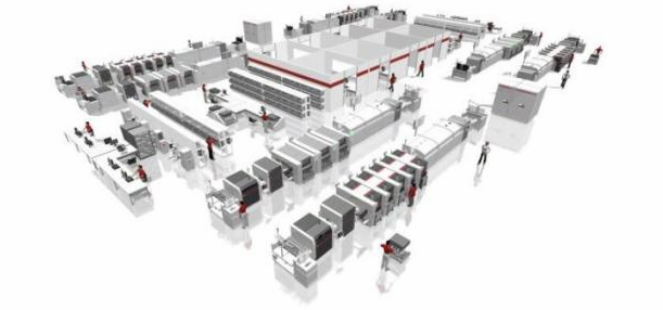
Its production process is very similar to the SMT process, that is, printing tin paste> inserting components> reflow soldering. Whether for single-sided mixed board or double-sided mixed board, it is the same process, as shown below:
Printing tin paste: Use a machine to print tin paste on the circuit board.
Manual plug-in machine: manual plug-in.
Spot solder reflow oven: use hot air reflow machine for soldering.
Finish
3. The characteristics of the through-hole reflow soldering process.
1. For some products with many SMT components and fewer perforated components, this process can replace wave soldering.

2. Advantages compared with wave soldering:
(1) The welding quality is good, and the defective ratio DPPM can be lower than 20.
(2) Few defects such as false soldering and even tin, and very low repair rate.
(3) The design of PCB Layout does not require special consideration like the wave soldering process.
(4) The process flow is simple, and the equipment operation is simple.
(5) The equipment occupies a small area. Because the printing machine and reflow furnace are small, it only needs a small area.
(6) The problem of Wuxi slag.
(7) The machine is fully enclosed, clean, and there is no peculiar smell in the production workshop.
(8)Equipment management and maintenance are simple.
3. The printing template is used in the printing process, and the soldering points and the amount of tin paste printed can be adjusted according to needs.
4. During reflow, a special template is used, and the temperature of each soldering point can be adjusted as required.
5. Disadvantages compared with wave soldering.
(1) Due to the use of tin paste in this process, the cost of solder is higher than that of wave soldering tin bars.
(2) Special special templates must be customized, which is more expensive. And each product needs its own set of printing templates and reflow soldering templates. It is not suitable for the simultaneous production of multiple different PCBA products.
(3) The reflow oven may damage components that are not resistant to high temperatures. When selecting components, pay special attention to plastic components, such as potentiometers, which may be damaged due to high temperature. According to our experience, general electrolytic capacitors, connectors, etc. are no problem. According to the results of our test, the surface of the component is actually used when the reflow oven is used. The maximum temperature is 120-150 degrees.
4. Through-hole reflow soldering process equipment.
1. Tin paste printing machine.
Machine used: tin paste printing machine). A special template is required to cooperate with the printing machine.
1.1 Basic principles.
Under a certain pressure and speed, use a plastic scraper to print the tin paste installed on the template through the leak on the template to the corresponding position on the circuit board. The steps are: feeding the circuit board --> mechanical positioning of the circuit board --->printing tin paste ---> sending out the circuit board
1.2 Schematic diagram of tin paste printing:
Scraper: No special requirements. The distance between the scraper and the template is 0.1-0.3mm, and the angle is 9 degrees.
Template: The thickness is 3mm, and the template is mainly composed of aluminum plate and many leaks.
Leakage nozzle: The function of the leakage nozzle is that the tin paste leaks to the circuit board through it. The number of leakage nozzles is the same as the number of component feet, and the position of the leakage nozzle is the same as the position of the component feet, so as to ensure that the solder paste leaks at the position of the component that needs to be soldered. The distance between the lower end and the PCB is 0.3mm, the purpose is to ensure that the tin paste can be easily printed on the PCB.
The size of the leak nozzle can be selected to meet the requirements of different solder volumes.
Printing speed: adjustable, the printing speed has a greater impact on the amount of tin paste printed on the PCB.
1.3 Process window:
Printing speed: After the machine is set up, only the printing speed can be adjusted electronically. To achieve good printing quality, the following points must be possessed:
1. The size of the drain nozzle is appropriate, too large will cause too much tin paste and short circuit; too small will cause too little tin paste and less tin.
2. The template has good flatness and no deformation.
3. The parameters are set correctly (mechanical settings):
(1) The distance between the lower end of the drain nozzle and the PCB is 0.3mm.
(2) The distance between the scraper and the template is 0.1-0.3mm, and the angle is 9 degrees.
2. Insert the component.
Use manual methods to insert electronic components into the circuit board, such as capacitors, resistors, power strips, switches, etc.
The component has been cut before insertion. There is no need to cut the pins after soldering. In wave soldering, the component pins are cut after soldering.
3. Spot solder reflow oven.
Machine used: reflow oven. A special template is required to be used with the reflow oven.
Stencil, stencil design is the focus of pupil reflow soldering. It is based on a lot of experience. Here are some examples
6. Temperature curve.
Due to the tin paste of through-hole reflow soldering, the component properties are completely different from SMT reflow, so the temperature profile is also completely different.
Temperature preheating zone, reflux zone, cooling zone
The temperature curve is divided into three areas:
A. Preheating zone.
The PCB circuit board is heated from room temperature to about 100OC-140OC, the purpose is to preheat the circuit board and tin paste to prevent the circuit board and tin paste from being thermally shocked in the welding zone. If there are components on the board that are not resistant to high temperatures, the temperature in this temperature zone can be lowered to avoid damage to the components.
B. Recirculation zone. (Main heating zone)
The temperature rises to the melting point of the tin paste and keeps it for a certain period of time to completely melt the tin paste. The maximum temperature is 200-230OC. The time above 178OC is 30-40 seconds.
C. Cooling zone.
With the help of a cooling fan, the temperature of the tin paste is reduced to form tin spots, and the circuit board is cooled to normal temperature.