In modern technology to achieve the miniaturization and simplification of smt processing technology, the required components to be used are becoming smaller and smaller, and the commonly used processing resistors, processing inductors and processing capacitors have become difficult to distinguish from the outside world. How to quickly distinguish common patch components?
The difference between smt processing faceted inductance and faceted capacitance;
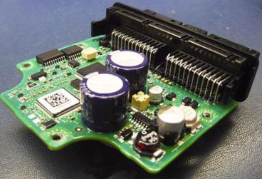
Color (black)-ordinary black is the chip inductor. Only the tantalum capacitors on the precision instrument are black, while other common chip capacitors are basically not black.
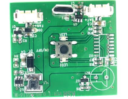
The patch inductance starts with l, and the patch capacitor should start with c. The preliminary judgment for the circular shape should be inductance. If the resistance at both ends exceeds 0 Euro, the inductance should be measured.

SMD inductors usually have low resistance, and there is no forward and backward shift of the multimeter pointer caused by "charge and discharge". The chip capacitor is charged and discharged.
If you look at a component, such as the internal structure, you can cut the component and view the internal structure. Chip inductors with coil structure.
According to different shapes, the inductance is polygonal, and the resistance is basically rectangular. The shape of the component to be distinguished is generally considered to be an inductance, especially in the case of a polygonal shape (especially a circular shape).
The resistance of the inductor for measuring the resistance value is small, and the resistance of the resistor is relatively large.
The difference between smt-processed chip capacitors and chip resistors is that the color of the chip capacitors is usually gray, blue-gray, and yellow, which is usually slightly brighter than the yellow in the case of hard copy. Some chip capacitors are mainly sintered at high temperatures and cannot be printed on the surface.
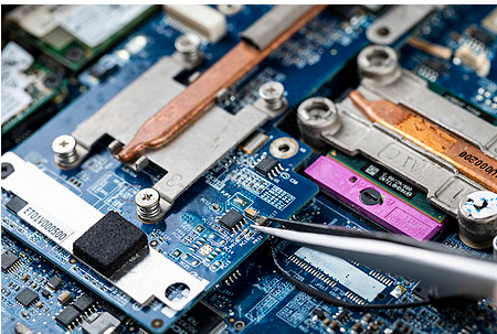
SMT patch processing and repair skills
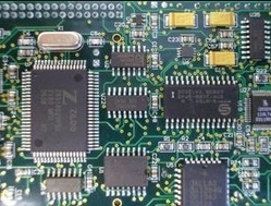
SMT patch processing and repair skills manual soldering should follow the principle of small first, then large, first low and then high, classify and solder in batches, solder chip resistors, chip capacitors, and transistors first, and then solder small IC devices and large ICs. Devices, and finally solder the interposing parts. When soldering chip components, the width of the soldering iron tip selected should be the same as the width of the component. If it is too small, it will be difficult to locate during assembly and soldering. When soldering SOP, QFP, PLCC and other devices with pins on two or four sides, SMT chip processing should first solder several positioning points on two or four sides. After careful inspection and confirmation that each pin is consistent with the corresponding pad, The drag soldering completes the soldering of the remaining pins. When dragging, the speed should not be too fast, just drag a solder joint in about 1 s. After soldering, you can use a 4-6 times magnifying glass to check whether there is a bridge between the solder joints. Where there is a bridge, you can use a brush to dip a little flux and then drag it again. The welding of the same part does not exceed 2 times, if it is not soldered once. Wait for it to cool before welding. When soldering IC devices, apply a layer of flux paste evenly on the pads, which not only can infiltrate and assist the solder joints, but also greatly facilitate the SMT patch processing and maintenance work and improve the repair speed. The two most critical processes for successful rework are preheating before welding and cooling after welding.