Inspection method of circuit board short circuit during SMT patch processing
In the manufacturing process of SMT patch processing PCB circuit boards, one of the defects that is easy to appear is short circuit. In order to avoid the short circuit of the circuit board from affecting the performance, it is necessary to check the circuit board and solve it in time. So how to check the short circuit of the PCB circuit board? Let’s find out below.
Inspection method of PCB circuit board short circuit:
1. Use short-circuit location analysis instrument.
2. Open the PCB board design drawing on the computer, light up the short-circuited network, and see where is the nearest, the easiest to connect to. Pay special attention to the short circuit inside the IC.
3. A short circuit is found. Take a board to cut the line (especially suitable for single/double-layer boards). After the line is cut, each part of the functional block is energized and eliminated step by step.

4. If there is a BGA chip, since all the solder joints are covered by the chip and cannot be seen, and it is a multi-layer board (above 4 layers), it is best to separate the power supply of each chip during the design, using magnetic beads or 0 ohms Resistor connection, so that when there is a short circuit between the power supply and the ground, the magnetic bead detection is disconnected, and it is easy to locate a certain chip. Because the welding of BGA is very difficult, if it is not automatically welded by the machine, a little carelessness will short-circuit the adjacent power supply and the ground two solder balls.
5. Be careful when welding small-size surface-mount capacitors, especially power supply filter capacitors (103 or 104), which are large in number, which can easily cause a short circuit between the power supply and the ground. Of course, sometimes with bad luck, the capacitor itself is short-circuited, so the best way is to test the capacitor before welding.
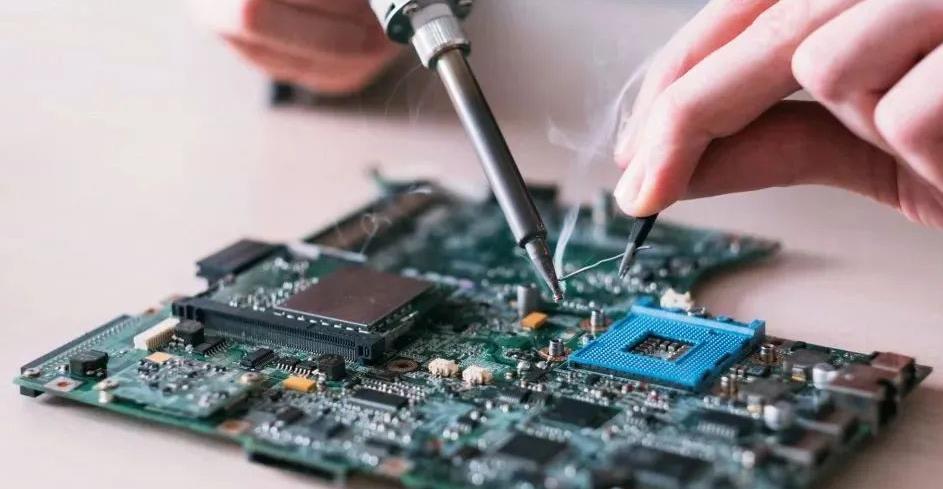
6. If it is manual soldering, develop a good habit: visually inspect the PCB board before soldering, and use a multimeter to check whether the key circuits (especially the power supply and ground) are short-circuited; use a multimeter to test every time a chip is soldered Check whether the power supply and ground are short-circuited; in addition, don't throw the soldering iron randomly.
SMT placement machine in the processing of incoming materials
SMT technology is the key to the assembly and production of SMT products. Under normal circumstances, solder paste printing and reflow soldering can complete the printing and soldering of the entire PCB at one time, while the placement of SMC/SMD must be automatically carried out by a placement machine, and the placement machine often needs to mount the SMD piece by piece. Therefore, the technical performance of the placement machine will directly affect the production efficiency and quality. The placement machine is the core and key equipment in the SMT product assembly line, and it determines the degree of automation of the electronic product assembly technology. The advanced level of the placement equipment fundamentally determines the two requirements of the placement process: placement accuracy and high placement rate.
What is patch processing? How does the placement machine work?
SMT is to take out the surface mount components such as SMC/SMD from its packaging structure, and then paste it on the designated pad position of the PCB. This process is called "Pick and Place" in English. Of course, the position of the solder pad must have been coated with solder paste, or although no solder paste has been applied, patch glue has been applied to the PCB surface covered by the components. After placement, the components rely on the adhesive force of solder paste or patch glue to initially stick to the designated pad position.
The basic process of using the placement machine to achieve the placement task is:
1. The PCB is sent to the workbench of the placement machine and fixed after optical alignment;
2. The feeder sends the components to be mounted into the suction start station of the placement machine, and the placement machine picks up sand to suck out the components from its packaging structure with an appropriate suction nozzle;
3. When the placement head sends the components to the PCB, the automatic optical inspection system of the placement machine cooperates with the placement head to complete tasks such as component detection and alignment correction;
4. After the placement head reaches the specified position, control the suction nozzle to accurately place the components on the specified pad position of the PCB with appropriate pressure, and the components are also glued with the coated solder paste and patch glue;
5. Repeat the above steps 2-4 until all the components to be mounted are placed, the PCB board with the components on it is sent out of the placement machine, and the entire placement machine is completed. The next PCB can be sent to the workbench again to start a new placement job.