SMT chip processing plant processing false welding, cold welding method
SMT chip processing plants may encounter false soldering, cold welding, and wicking problems during the processing of lead-free chips. So how can the chip processing plant solve these problems?
The first is the problem of false soldering, which is usually caused by the following reasons: poor solderability of components and pads, improper reflow soldering temperature and heating speed, incorrect printing parameters, too long stagnation time after printing, and change in solder paste activity Poor and other reasons.
The solution is as follows: strengthen the screening of PCB and components to ensure good soldering performance; adjust the reflow soldering temperature curve; change the pressure and speed of the squeegee to ensure a good printing effect; solder paste as soon as possible after printing and reflow soldering.
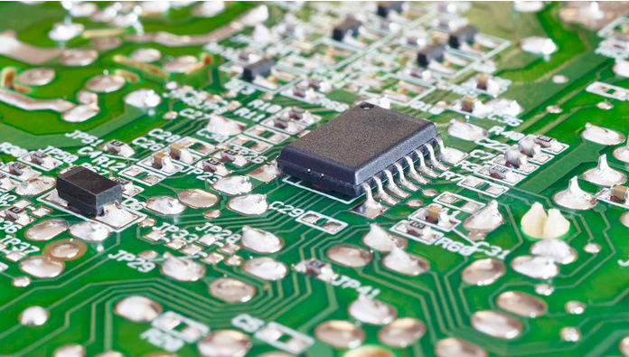
Next is the problem of cold welding. The so-called cold welding means that the surface of the solder joint is dark and rough, and it does not melt with the object to be welded. Generally speaking, the formation of cold welding in SMT chip processing is mainly caused by unsuitable heating temperature, deterioration of solder, and excessive preheating time or high temperature.

General solution: adjust the curve according to the reflux temperature curve provided by the supplier, and then adjust it according to the actual situation of the produced product. Replace with new solder paste. Check whether the equipment is normal and correct the preheating conditions.
Another problem is wicking. Sn/Pb solder paste rarely occurs before, but this problem often occurs when using lead-free solder paste. This is mainly because the wetting and spreading rate of lead-free solder paste is not as good as that of lead-containing solder paste. The main reason for the wicking phenomenon is the high thermal conductivity of the component pins and the rapid temperature rise, so that the solder preferentially wets the pins, and the wetting force between the solder and the pin is much greater than the wetting force between the solder and the pad., The upturn of the lead will aggravate the occurrence of wicking phenomenon.
The general solution: during reflow soldering, the SMA should be fully preheated and then placed in the reflow oven to carefully check and ensure the solderability of the PCB board pads. The coplanarity of the soldered components cannot be ignored. Defective devices should not be used in production.
SMT patch processing technology assembly method
On the traditional THT printed circuit board, the components and solder joints are located on both sides of the board, while on the Kunshan SMT chip printed circuit board, the solder joints and components are on the same side of the board. Therefore, in the SMT patch printed circuit board, the through holes are only used to connect the wires on both sides of the circuit board. The number of holes is much smaller, and the diameter of the holes is much smaller, so the assembly density of the circuit board can be greatly increased. improve.
Choosing an appropriate assembly method according to the specific requirements of the assembled product and the conditions of the assembly equipment is the basis for efficient and low-cost assembly and production, and it is also the main content of the SMT chip processing process design. The so-called surface assembly technology refers to the chip structure components or miniaturized components suitable for surface assembly, placed on the surface of the printed board according to the requirements of the circuit, and assembled by soldering processes such as reflow soldering or wave soldering, Constitute the assembly technology of electronic components with certain functions.
On the conventional THT printed circuit board, the components and solder joints are located on both sides of the board, while on the SMT patch printed circuit board, the solder joints and components are on the same side of the board. Therefore, in the SMT patch printed circuit board, the through holes are only used to connect the wires on both sides of the circuit board. The number of holes is much smaller, and the diameter of the holes is much smaller, so the assembly density of the circuit board can be greatly increased. improve. The following editor organizes and introduces the assembly method of SMT patch processing technology.
1. SMT single-sided hybrid assembly method
The first type is single-sided mixed assembly, that is, SMC/SMD and through-hole plug-in components (17HC) are distributed on different sides of the PCB, but the welding surface is only one-sided. This type of assembly method uses single-sided PCB and wave soldering (currently double wave soldering is generally used), and there are two specific assembly methods.
(1) Paste first. The first assembly method is called the first-attach method, that is, the SMC/SMD is attached to the B side (welding side) of the PCB first, and then the THC is inserted on the A side.
(2) Post-posting method. The second assembly method is called post-attachment method, which is to first insert THC on the A side of the PCB, and then mount the SMD on the B side.
2. SMT double-sided hybrid assembly method
The second type is double-sided hybrid assembly. SMC/SMD and T.HC can be mixed and distributed on the same side of the PCB. At the same time, SMC/SMD can also be distributed on both sides of the PCB. Double-sided hybrid assembly adopts double-sided PCB, double wave soldering or reflow soldering. In this type of assembly method, there is also a difference between SMC/SMD or SMC/SMD. Generally, it is reasonable to choose according to the type of SMC/SMD and the size of the PCB. Usually, the first-sticking method is more adopted. Two assembly methods are commonly used in this type of assembly.
(1) SMC/SMD and iFHC are on the same side, SMC/SMD and THC are on the same side of the PCB.
(2) SMC/SMD and iFHC have different side methods, put the surface mount integrated chip (SMIC) and THC on the A side of the PCB circuit board, and put the SMC and small outline transistor (SOT) on the B side.
In this type of assembly method, the SMC/SMD is mounted on one or both sides of the PCB, and the leaded components that are difficult to be surface-assembled are inserted into the assembly, so the assembly density is quite high.
The assembly method and process flow of SMT chip processing mainly depend on the type of surface mount component (SMA), the types of components used and the conditions of assembly equipment. In general, SMA can be divided into three types of single-sided mixed assembly, double-sided mixed assembly and full-surface assembly, a total of 6 assembly methods. Different types of SMA have different assembly methods, and the same type of SMA can also have different assembly methods.