The printed circuit board is often referred to as the PCB. The components on the PCB are called the circuit board assembly or PCBA. The components on the board can be SMT (surface mount) components, plug-in components, pressure components or assemblies. In the previous article, I shared the SMT solder paste printing technology of PCBA (circuit board assembly), and today I shared the SMT technology and common problems of PCBA.
Compared with plug-in components, SMT components have many advantages. Small size, low height, automatic production, good high-frequency characteristics, and low cost. SMT components are surface-mounted, avoiding the internal PCB traces, and are widely used in some high-end products. SMT components are relatively short, providing competitiveness for many current customers who are pursuing thinner products. In the production, the placement machine is used for automatic placement, which greatly improves the production efficiency. Its no-pin or short-pin design improves high-frequency characteristics and has good stability. In addition, low cost is also the eternal pursuit of manufacturers.
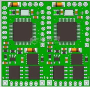
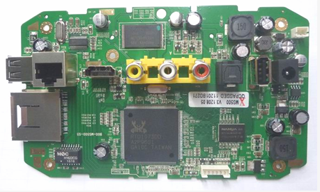
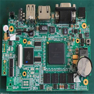
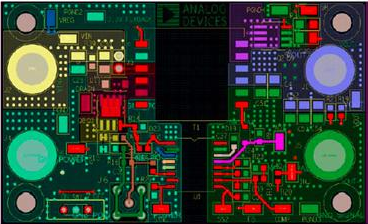
SMT patch process example

The types of SMT components are now very rich, including capacitors, resistors, inductors, diodes, transistors, ICs, connectors, crystals, screws, etc. Basically all components can be made into SMT types. The number of MLCC capacitors on PCBA is the largest. Due to space constraints, some capacitors are made smaller and smaller, from the most typical 0402 MLCC capacitor to 01005 size. Such a small resistance and capacitance have extremely high requirements on the placement machine, reflow soldering, and the opening of the steel mesh.
ICs with various packaging forms have evolved from the commonly used SOP at the beginning to QFP, QFN, etc., and then to BGA. The component changes from lead to no lead, and the soldering position is from two sides to four sides, and then develops into a solder ball on the bottom and top of the component. The number of solder joints ranges from 4 for SOP components to more than 3,000 for BGA components. These changes fully demonstrate the advancement in design and production processes of component and PCBA manufacturers.
The process of SMT placement has also changed. At first, after printing the solder paste, red glue is applied on the PCB, then the patch, and finally the plug-in components are soldered together by wave soldering. Up to now, there is no need to dispense red glue, SMT directly prints the solder paste, then mounts, and reflow soldering is enough.
Based on placement efficiency and quality considerations, large PCBAs generally use several placement machines to complete the placement process. The general rule is to use a high-speed placement machine to paste some chip components, such as resistors, capacitors, inductors, etc., and then paste crystals, transistors, LEDs, small ICs, etc. Some large components such as BGA type ICs, large connectors such as memory slots, etc. are arranged in the final multi-function placement machine. The number of components selected by the nozzle of the placement machine at a time, the location of the placement, etc., can be designed according to the performance of the placement machine and the layout of the PCBA components.
The most common problems in the SMT patch production process are component reverse, offset, few parts, and occasionally damaged parts, multiple parts and so on. In the NPI stage of trial production of new products, due to insufficient understanding of the polarity of the product components, there may be problems with batches of polar components, such as diodes, LEDs, and ICs. These can be found and corrected in the first article inspection FAI. The problem of misalignment can be solved by adjusting the coordinates and height of the part. When the suction nozzle of the placement machine is dirty or damaged, resulting in insufficient vacuum, the problem of missing pieces will occur. Components that fall in the middle of the journey sometimes fall onto the PCB board, causing multiple abnormalities in a certain position.
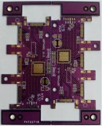
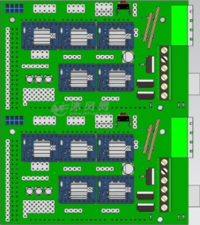
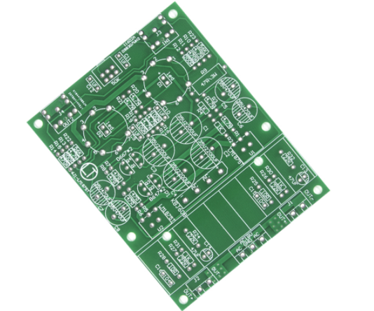
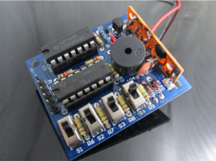
Examples of missing parts for SMT components
Another type of catastrophic anomaly is a damaged part. Even if the factory has many test and inspection processes, such as automatic optical inspection AOI, online ICT test, functional test BFT, and manual appearance inspection, these processes cannot fully detect the damaged parts caused by the placement process. There are some damaged parts of MLCC capacitors that cannot be seen in appearance, and even function normally in the short term. Only in the slice experiment or long-term use process will the abnormality appear. Excessive pressure or low height of the suction nozzle may cause damage to the chip components. When SMT components on the same product are supplied by multiple manufacturers, pay special attention to whether there are differences in the thickness of components from different manufacturers.