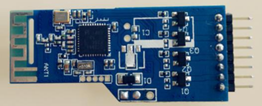
If the SMT placement machine is a robot, the placement head is an intelligent manipulator. Through program control, the position is automatically corrected, the components are picked up according to the regulations, and they are accurately placed on the preset pads to complete the three-dimensional reciprocating motion. It is the most complex and critical part of the placement machine. The placement head is composed of suction nozzles, visual alignment systems, sensors and other components.
There are two types of placement heads: single-head and multi-head. Multi-head placement heads can be divided into fixed and rotary types. After the suction nozzle of the initial single-head placement machine sucked a component, it realized the component centering according to the mechanical centering mechanism and gave a signal to the feeder to make the next component enter the suction position. However, the placement rate of this method is relatively slow, and it usually takes 1S to place a chip component. Therefore, in order to increase the patch rate, people adopt the method of increasing the number of patch heads, that is, use several patch heads to increase the patch rate. The multi-head placement machine has increased from a single head to 3 to 6 placement heads, instead of using mechanical alignment, it has been improved to various forms of optical alignment. Components are picked up during work, and then placed on the PCB in turn after alignment. At the designated location. At this stage, the patch rate of this model has reached the level of 30,000 components per hour, and the price of this machine is relatively low and can be used in combination. Rotary multi-head structure can also be used. At this stage, the patch rate of this method has reached 45,000 to 50,000 pieces per hour.

(1) Suction nozzle. At the end of the placement head, there is a placement tool controlled by a vacuum pump, that is, a suction nozzle. Components of various shapes and sizes are often picked and placed using various suction nozzles. After the vacuum is generated, the negative pressure of the suction nozzle sucks the SMD components from the feeding system (bulk silo, tubular hopper, disc-shaped paper tape or tray packaging). The suction nozzle needs to reach a certain degree of vacuum when sucking the film. Only then can it be judged whether the picked up components are normal. When the component stands on its side or fails to be sucked up due to the component "cartridge", the placement machine will send out an alarm signal. The moment the pick-up nozzle picks up the components and places them on the PCB, two methods are usually used for placement. One is based on the height of the component, that is, the thickness of the component is input in advance. When the placement head is lowered to this height, the vacuum is released and the component is placed on the pad. When using this method, due to individual differences in components or PCBs, the phenomenon of early or late placement may occur, and in serious cases, it may cause component displacement or flying chip defects. Another more professional method is to realize the soft landing of the placement under the action of the pressure sensor based on the instantaneous reaction of the component and the PCB. Therefore, the placement is easy, and it is not easy to cause displacement and flying chip defects.
The suction nozzle is a component that directly touches the SMT components. In order to adapt to the placement of various components, many placement machines will also be equipped with a device for removing and replacing the suction nozzle. There is also an elastic compensation between the suction nozzle and the suction tube. The buffer mechanism ensures the protection of the patch components during the picking process.
The suction nozzle touches the components during high-speed movement, and its wear is very serious. Therefore, the material and structure of the suction nozzle are becoming more and more important. In the early days, alloy materials were used, and then changed to carbon fiber wear-resistant plastic materials. The more professional nozzles use ceramic materials and diamonds to make the nozzles more durable.
With the miniaturization of SMT components and the reduction of the gap with surrounding components, the structure of the suction nozzle has also been relatively adjusted. A hole is opened on the suction nozzle to ensure that it is stable when picking up small components such as 0603. It is easy to mount and place without affecting the surrounding components.
(2) Visual alignment system. With the increasing demand for small, light, thin and high reliability of electronic products, only the precise placement of fine-pitch components can ensure the reliability of surface assembly. To accurately mount fine-pitch components, the following factors are usually considered.
1. PCB positioning deviation. Under normal circumstances, the circuit pattern on the PCB does not always correspond to the machining holes of the PCB mechanical positioning and the PCB edge, which will cause mounting deviation. In addition, defects such as distortion of the circuit pattern on the PCB, PCB deformation and warpage will cause mounting deviation.
2. The centering deviation of the components. The centerline of the component itself does not always correspond to the centerline of all the leads, so when the placement system uses the mechanical centering claw to center the component, it may not be able to align the centerline of all the leads of the component. In addition, in the packaging container, or when the centering claw is clamped and centered, the component leads may be bent, twisted, and overlapped, that is, the leads lose coplanarity. Such phenomena will cause placement deviation and reduced placement reliability. Surface mounting is successful when the lead of the component deviates from the pad by no more than 25% of the lead width. When the lead pitch is narrow, the allowable deviation is smaller.
3. The movement deviation of the machine itself. The mechanical factors that affect the placement accuracy are: the X-Y axis movement accuracy of the placement head or PCB positioning table, the accuracy of the SMT component centering mechanism and the placement accuracy. The vision system has become an important part of the high-precision placement machine.