SMT patch check short circuit skills
In the manual soldering process of SMT patch, short circuit is a relatively common processing defect. To achieve the same effect as manual SMT patch and machine pasting, short circuit is a problem that must be solved. Short-circuit PCBA cannot be used. There are many ways to solve short-circuit in SMT patch processing. The following is a brief introduction about SMT patch processing.
In the manual soldering process of smt patch, short circuit is a relatively common processing defect. To achieve the same effect as manual SMT patch and machine pasting, short circuit is a problem that must be solved. Short-circuit PCBA cannot be used. There are many ways to solve short-circuit in SMT patch processing. The following is a brief introduction about SMT patch processing.
Method to solve device cracking in SMT chip processing

1. To develop a good habit of manual welding operation, use a multimeter to check whether the key circuit is short-circuited. Every time you manually SMT an IC, you need to use a multimeter to measure whether the power supply and the ground are short-circuited.
2. Light up the short-circuited network on the PCB diagram, look for the place on the circuit board that is most likely to be short-circuited, and pay attention to the internal short-circuit of the IC.
3. If there is a short circuit in the same batch in SMT patch processing, you can take a board to cut the line, and then power on each part to check the short circuit.
4. Use a short-circuit location analyzer to check.
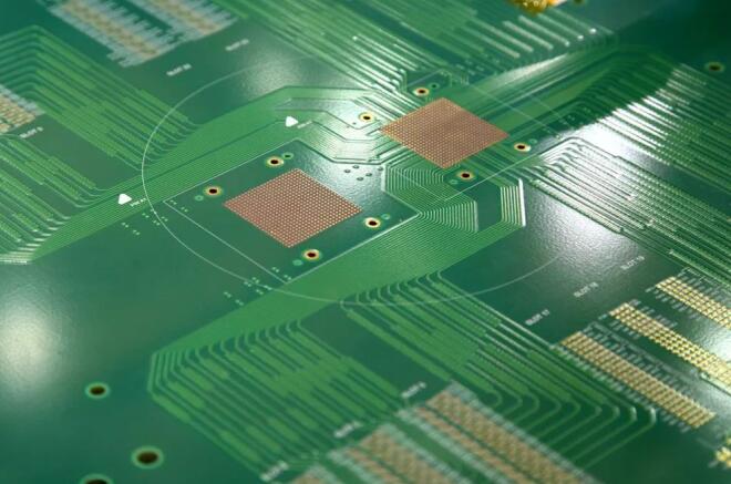
5. If there is a BGA chip, since all the solder joints are covered by the chip and cannot be seen, and it is a multi-layer board (above 4 layers), the power supply of each chip is divided during the design and connected with magnetic beads or 0 ohm resistors., In this way, when there is a short circuit between the power supply and the ground, the magnetic bead detection is disconnected, and it is easy to locate a certain chip.
6. Be careful when welding small-size SMT patch processing surface-mount capacitors, especially the power supply filter capacitors (103 or 104), which are large in number, which can easily cause a short circuit between the power supply and the ground. !
Method to solve device cracking in SMT chip processing
In SMT chip processing and assembly production, the cracking of chip components is common in multilayer chip capacitors (MLCC). The cause of MLCC cracking failure is mainly due to stress, including thermal stress and mechanical stress, which is thermal stress Cracking of MLCC devices caused by chip component cracking often occurs in the following situations.
In the production of smt patch processing and assembly, the cracking of chip components is common in multilayer chip capacitors (MLCC). The cause of MLCC cracking failure is mainly due to stress, including thermal stress and mechanical stress, that is, thermal stress Cracking of MLCC devices caused by chip component cracking often occurs in the following situations.
1. Where MLCC capacitors are used: For this capacitor, its structure is superimposed by multilayer ceramic capacitors, so its structure is fragile, low in strength, and extremely resistant to heat and mechanical shocks. This is especially true during wave soldering. obvious.
2. During the placement process, the suction and release height of the Z-axis of the placement machine, especially some placement machines that do not have the Z-axis soft landing function, the absorption height is determined by the thickness of the chip component, not by the pressure sensor, So the component thickness tolerance will cause cracking.
3. After soldering, if there is warping stress on the PCB, it will easily cause the components to crack
4. The stress of the split PCB will also damage the components.
5. The mechanical stress during the ICT test causes the device to crack.
6. The stress generated by the tightening screw during the assembly process will damage the surrounding MLCC.
In order to prevent chip components from cracking, the following measures can be taken:
1. Carefully adjust the welding process curve, especially the heating rate should not be too fast.
2. Make sure that the placement machine pressure is appropriate during placement, especially for thick plates and metal substrate plates, and ceramic substrates when mounting MLCC and other brittle devices.
3. Pay attention to the sorting method and the shape of the cutter when making up.
4. For the warpage of the PCB, especially the warpage after soldering, targeted corrections should be made to avoid the influence of the stress caused by large deformation on the device.
5. MLCC and other devices should avoid high stress areas when laying out the PCB board.